
Self-centering compact damper unit applicable to structures for seismic energy dissipation

a damper unit and compact technology, applied in the direction of bridges, shock proofing, bridge structural details, etc., can solve the problems of internal residual displacement and difficulty in applying it in bridge structures which have already been constructed

Inactive Publication Date: 2011-10-06
NAGOYA INSTITUTE OF TECHNOLOGY
View PDF3 Cites 29 Cited by
  • Summary
  • Abstract
  • Description
  • Claims
  • Application Information

AI Technical Summary

Benefits of technology

[0010]In view of the above, one of objects of the present invention is to provide a compact self-centering damper unit which can solve the problems described above, by generating a self-centering mechanism within the damper unit itself.
[0034]These features allow the left and right columns to rotatably move more smoothly relative to the upper and lower beams.
[0046]In this case, it is preferable that the shear panel has a planar shape being substantially the same rectangular shape as a shape defined by an inside portion of the frame, and four corners of the shear panel are cut out. This feature allows the shear panel to deform more smoothly because the shear panel has cut out potions, as described later in more details.

Problems solved by technology

However, the structural members including dampers go into plastic state, and therefore, the residual displacement retains within the frame structure after major earthquakes.
However, the post-tensioned steel bar needs to pass through the long column of the civil engineering construction.
Rather, it is difficult to apply it in the bridge structures which have already been constructed.

Method used


Image

  • Self-centering compact damper unit applicable to structures for seismic energy dissipation
  • Self-centering compact damper unit applicable to structures for seismic energy dissipation
  • Self-centering compact damper unit applicable to structures for seismic energy dissipation

Examples


first embodiment

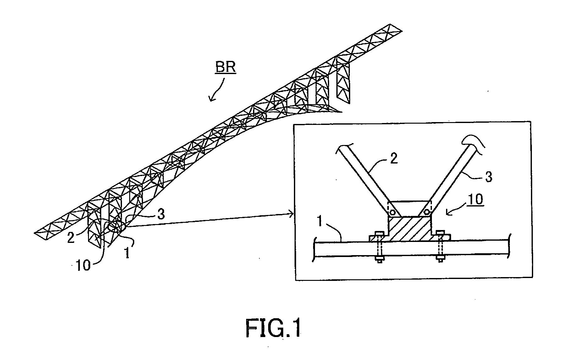
[0074]FIG. 1 shows an example of an application of the self-centering compact damper unit 10 (hereinafter, referred to as “a first damper unit 10”) according to a first embodiment of the present damper unit. In the example, the first damper unit 10 is applied to an arch bridge BR.

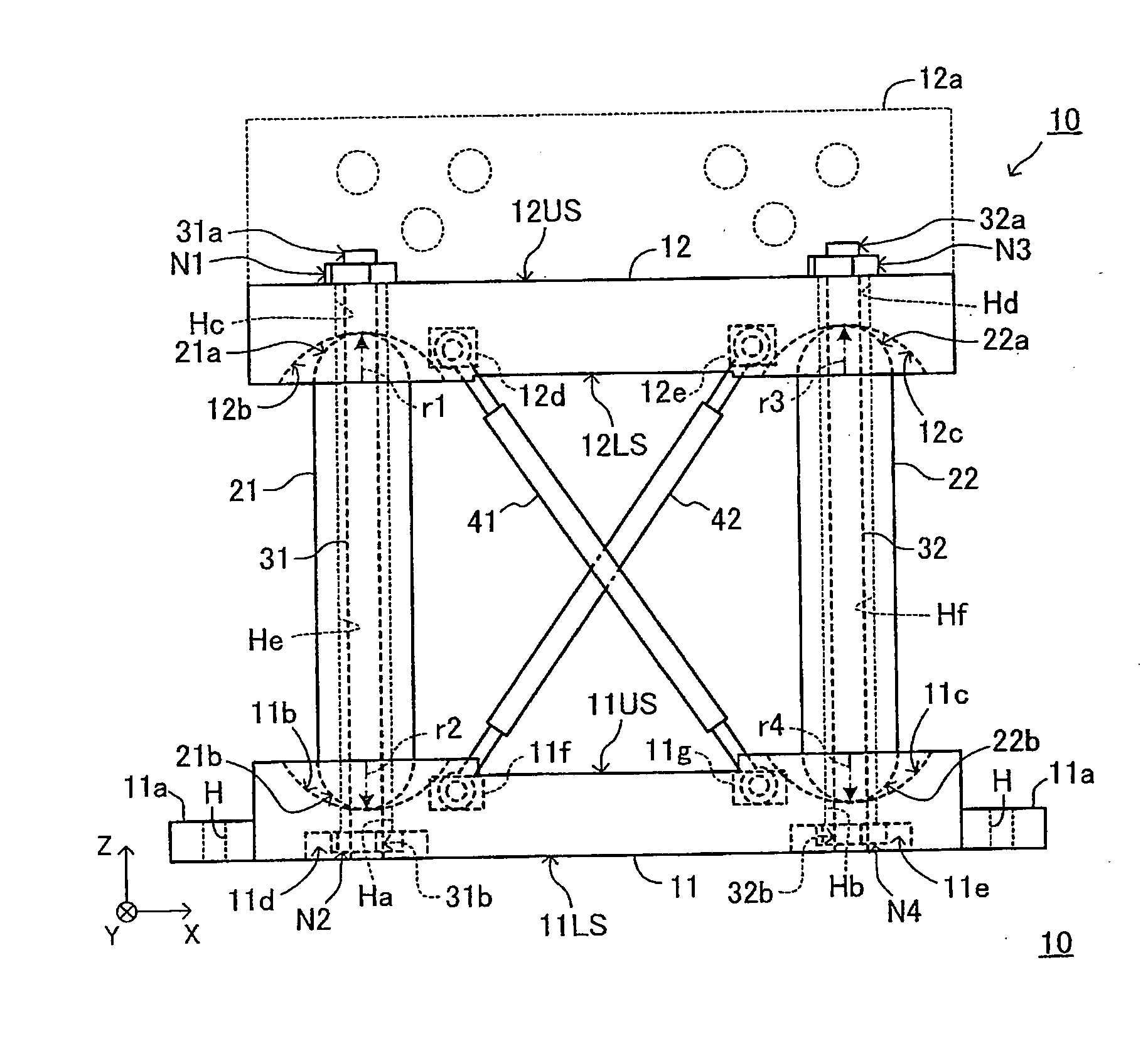
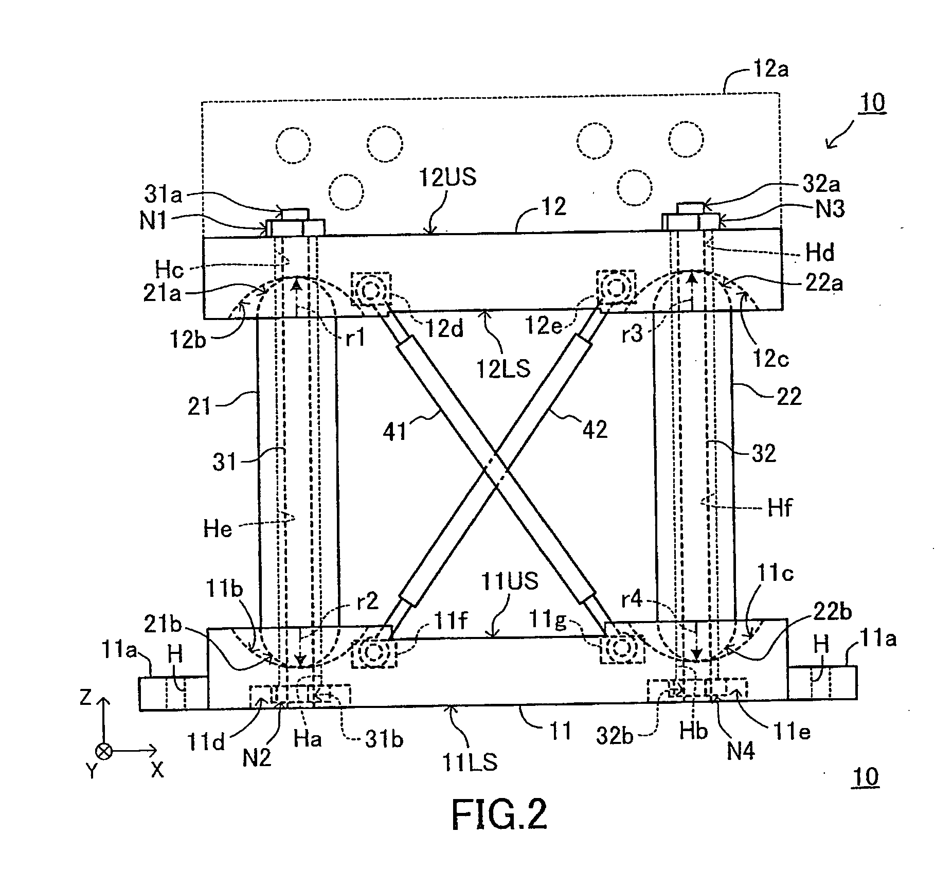
[0075]The first damper unit 10 is disposed among bridge members 1, 2, and 3. A lower portion of the first damper unit 10 is rigidly connected with the arch bridge member 1. An upper portion of the first damper unit 10 is rigidly connected with the bridge members 2 and 3. The seismic force is transmitted through the arch bridge members 1, 2, and 3 to the first damper unit 10. It should be noted that, in a conventional bridge in which the first damper unit 10 is not used, the bridge members 2 and 3 are rigidly connected with the bridge member 1 directly.

[0076]As shown in FIGS. 2, 3, and 4, the first damper unit 10 comprises a lower beam 11, an upper beam 12, a left column 21, a right column 22, a left post-te...

second embodiment

[0133]FIG. 8 shows a self-centering compact damper unit 50 (hereinafter, referred to as “a second damper unit 50”) according to a second embodiment of the present invention. The second damper unit 50 can also be applied to the arch bridge BR or other structures, similarly to the first damper unit 10.

[0134]The second damper unit 50 is different from the first damper unit 10 only in that the second damper unit 50 comprises a shear panel 60, in place of the first and second axially yielding dampers 41, 42, as an energy dissipating means.

[0135]The shear panel 60 has a substantially rectangular shape. More specifically, the shear panel 60 has a planar shape which is substantially the same rectangular shape as a shape defined by an inside portion of the frame. Four corners of the shear panel 60 are cut out. A shape of each of the cut-out portions 61-64 is substantially a quarter circle, but may be another shape including a triangle.

[0136]The shear panel 60 is disposed in the frame, and is...


PUM


Abstract

The damper unit 10 is applicable to structures for seismic energy dissipation. The damper unit 10 comprises, a lower beam 11, an upper beam 12, a left column 21, a right column 22, axially yielding dampers 41, 42 functioning as an energy dissipating means, a left post-tensioned steel bar 31, and a right post-tensioned steel bar 32. The left and right post-tensioned steel bars 31 and 32 are inserted in the left and right columns 21 and 22, respectively. Upper ends of the steel bars 31 and 32 are connected with the upper beam 12. Lower ends of the steel bars 31 and 32 are connected with the lower beam 11. The columns 31 and 32 are semi-rigid connected with the upper beam 12 and the lower beam 11 by compressive forces generated from the steel bars 31 and 32. Therefore, the damper unit 10 possesses both self-centering and seismic energy dissipation characteristics.

Description

BACKGROUND OF THE INVENTION[0001]1. Field of the Invention[0002]The present invention relates to a self-centering compact damper unit applicable to structures for seismic energy dissipation.[0003]2. Description of the Related Art[0004]There have been developed various seismic resistant systems with using dampers, braces, and so on.[0005]For example, Japanese Unexamined Patent Application Publication No. 2001-220709 (corresponding U.S. Pat. No. 6,722,088) discloses a seismic resistant frame structure comprising a pair of bridge columns, a beam, a pair of brace members, and a hysteretic damper (shear damper). The beam is supported by the columns. The damper is connected at a middle position of the beam. One end of each of the brace members is pin-connected at a middle position of each of the columns. The other end of each of the brace members is connected with the damper. The braces therefore form a reversed V shape.[0006]Japanese Unexamined Patent Application Publication No. 2008-303...

Claims


Application Information

Patent Timeline
IPC IPC(8): E04B1/98
CPCE01D21/00E04H9/024E01D19/00F16F15/02
Inventor GOTO, YOSHIAKIKUMAR, GHOSH PROSENJITEBISAWA, TAKEMASA
Owner NAGOYA INSTITUTE OF TECHNOLOGY
Learn More