Method of Manufacturing Lapping Plate, and Method of Manufacturing Magnetic Head Slider using the Lapping Plate

a technology of lapping plate and lapping plate, which is applied in the direction of grinding device, grinding device, abrasive surface conditioning device, etc., can solve the problems of serious harm to the productivity of the magnetic head element itself, and achieve the effect of small height variation and large abrasive grain heigh

Inactive Publication Date: 2011-10-06
HITACHI LTD
View PDF0 Cites 6 Cited by
  • Summary
  • Abstract
  • Description
  • Claims
  • Application Information

AI Technical Summary

Benefits of technology

Since a lapping plate is manufactured through the abrasive digging process using an unwoven cloth or the like having an irregular surface and through the subsequent abrasive peak equalization process using a ceramic substrate or the like; there is obtained a lapping plate which has a large abrasive grain height and a small height variation, or in other words, which can maintain a smooth lapping surface to a lapping target over a long period of time.

Problems solved by technology

However, when the lapping rate becomes extremely small, a lapping time until a flat and smooth air hearing surface is achieved becomes abnormally long, which leads to a serious harm in the productivity of the magnetic head element itself.

Method used


Image

  • Method of Manufacturing Lapping Plate, and Method of Manufacturing Magnetic Head Slider using the Lapping Plate
  • Method of Manufacturing Lapping Plate, and Method of Manufacturing Magnetic Head Slider using the Lapping Plate
  • Method of Manufacturing Lapping Plate, and Method of Manufacturing Magnetic Head Slider using the Lapping Plate

Examples


Embodiment Construction

An embodiment of the present invention will be explained in detail with reference to accompanying drawings.

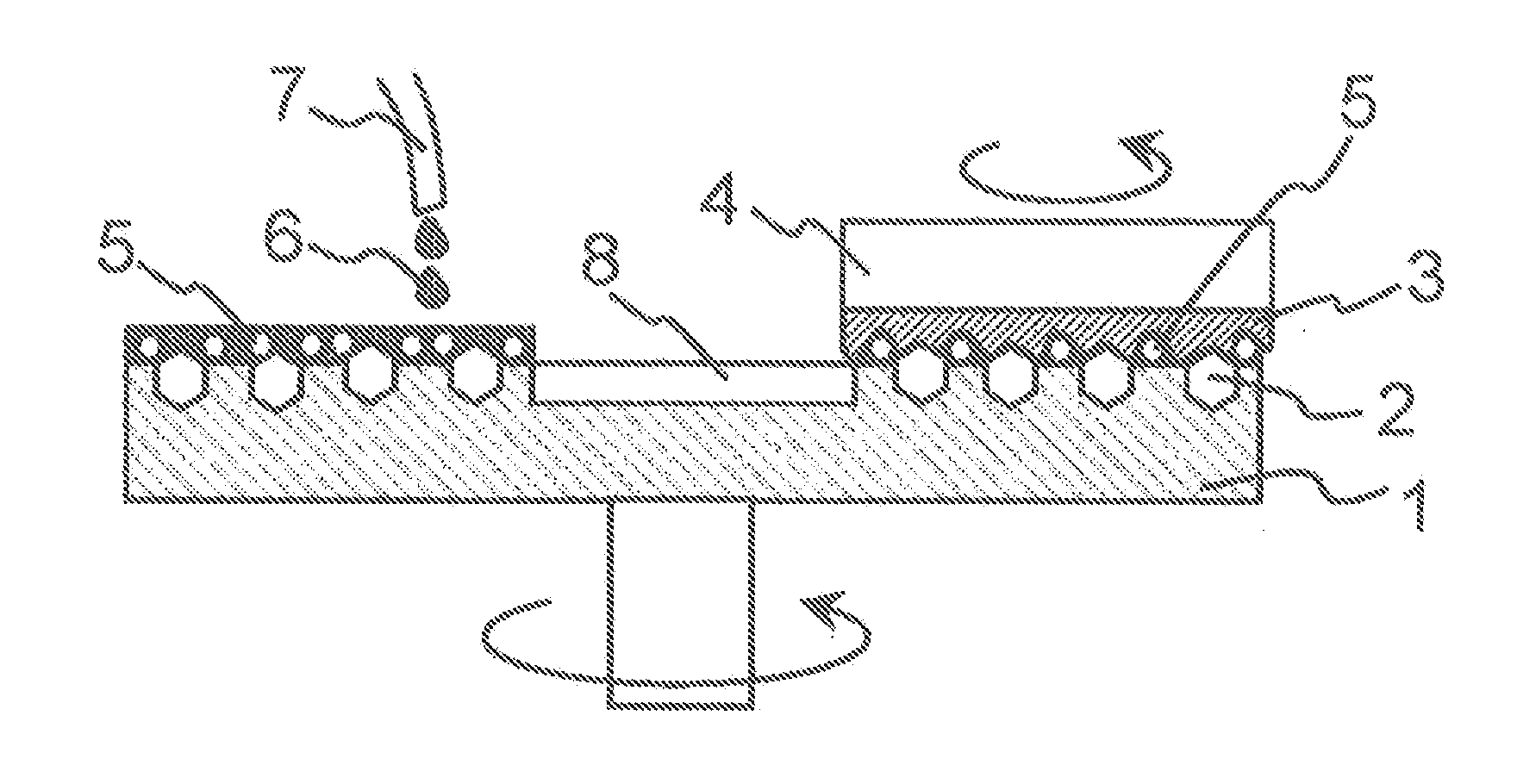
FIG. 1 is a schematic diagram for explaining an abrasive digging process in the present invention. In FIG. 1, diamond abrasive grains 2 (which will be referred to as first abrasive grains, hereinafter, unless otherwise stated) are embedded and fixed in one surface of a lapping plate 1 using an abrasive grain fixing tool already known in the art. A recess 8 is formed in the center of the lapping plate 1, and a hole (not shown) for discharging a lapping lubricant 6 supplied to the recess 8 is provided in the recess 8.

While the lapping lubricant 6 with abrasive grains 5 (which will be referred to as second abrasive grains, hereinafter unless otherwise stated) is supplied from a supply tube 7 onto the surface of the lapping plate 1, a dressing tool 4 having an unwoven cloth 3 applied to its surface is rotated and pushed against the surface of the lapping plate 1. As a result, under...


PUM

PropertyMeasurementUnit
grain sizeaaaaaaaaaa
abrasive grain heightaaaaaaaaaa

Abstract

A method of manufacturing a lapping plate which has abrasive grains fixed in the plate and which is used for lapping of the air bearing surface of a magnetic head. Abrasive grains fixed in the lapping plate are subjected to an abrasive digging process to selectively lap the surface of the lapping plate in the vicinity of the abrasive grains, and the dug abrasive grains are subjected to an equalization process to make their abrasive grain heights equal.

Description

INCORPORATION BY REFERENCEThe present application claims priority from Japanese application JP2010-080099 filed on Mar. 31, 2010, the content of which is hereby incorporated by reference into this application.BACKGROUND OF THE INVENTIONThe present invention relates to a method of manufacturing a lapping plate having diamond abrasive grains fixed therein and also a method of manufacturing a magnetic head slider using the lapping plate.In these years, as the quantity of information handled by a magnetic disk device is increased, a demand of a higher recording density to the disk became rapidly strong. In order to serve the demand, it becomes vital to increase a detection sensitivity for a signal when recorded information is read out from or written in a magnetic recording medium of a magnetic head and also to increase the output of the signal by further reducing a flying height for the magnetic recording medium. In order to further reduce the flying height, it becomes indispensable to...

Claims


Application Information

Patent Timeline
Patent Type & Authority Applications(United States)
IPC IPC(8): G11B5/84B24D18/00B24D3/00B24B37/12B24B53/017B24D3/06G11B5/31
CPCB24B37/11G11B5/102G11B5/3166Y10T29/49048G11B5/3173G11B5/8404G11B5/3169
Inventor FUKUOKA, NOBUHIKOKOJIMA, HIROYUKISASAKI, SHINJITAMURA, TOSHIO
Owner HITACHI LTD
Why Eureka
Try Eureka