
High/low bracket placements on lingual surfaces

a technology of brackets and lingual surfaces, applied in the field of orthodontic brackets and wire systems, to achieve the effect of adding rigidity and shortening the span of teeth not connected

Active Publication Date: 2011-09-29
LEMCHEN MARC S
View PDF12 Cites 0 Cited by
  • Summary
  • Abstract
  • Description
  • Claims
  • Application Information

AI Technical Summary

Benefits of technology

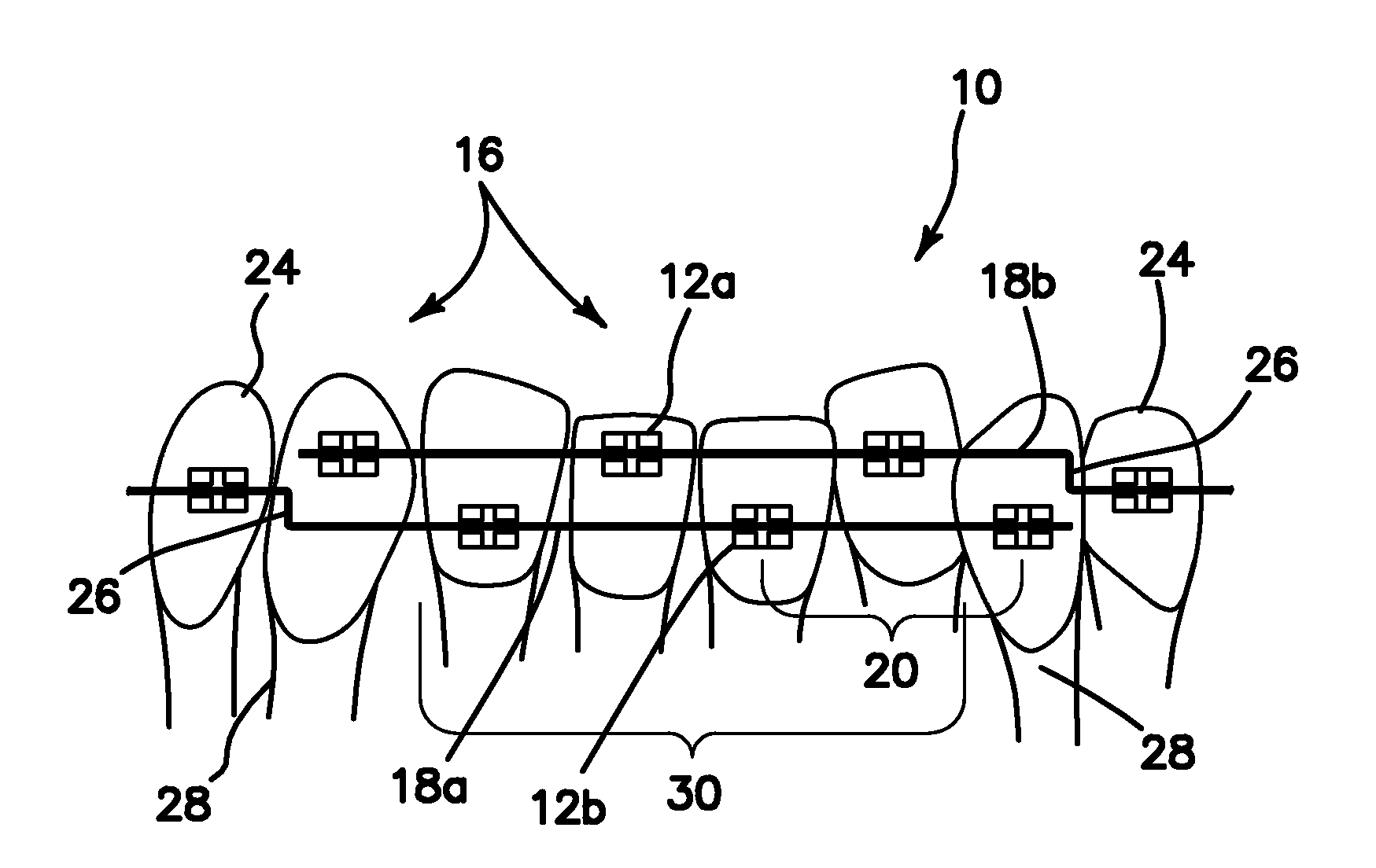
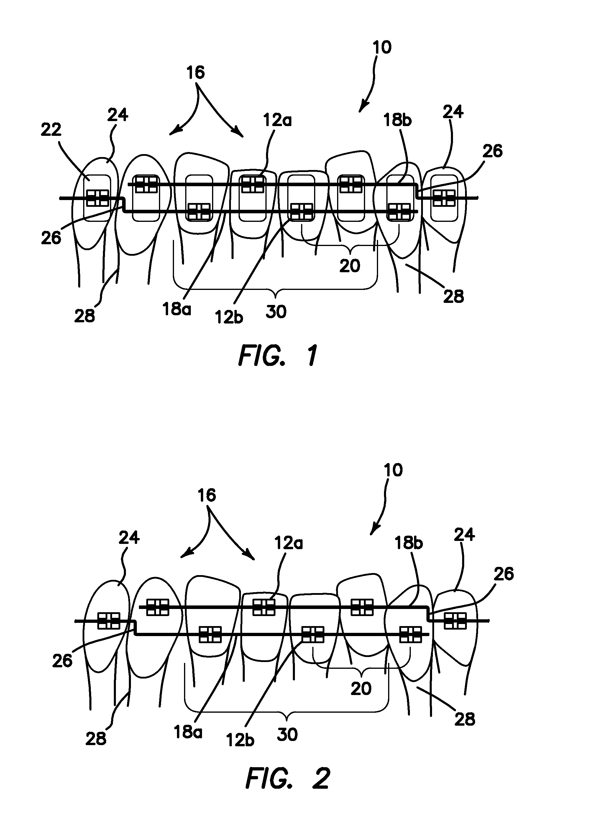
[0011]In one embodiment the cuspid bracket is a bracket with a slot or attachment point for a single wire reflecting the position of the tooth distal to it, or any other predetermined height, or with a double slotted bracket with one slot corresponding to the height of the tooth distal to it or another predetermined height, and the other slot corresponding to the height of the wire coming from the opposing side, so that the wire terminates in the cuspid bracket. A double slotted cuspid bracket with one high slot and one low slot may be used in cases where adequate space exists between the cuspid and lateral for a bend or none is required. In this way in selected cases we could shorten the span of teeth not connected and add rigidity to the anterior segment.

Problems solved by technology

Otherwise the bend would have to be so small and rigid that engaging the wire would permanently deform it rendering it unusable.

Method used


Image

  • High/low bracket placements on lingual surfaces
  • High/low bracket placements on lingual surfaces

Examples


Embodiment Construction

[0018]The illustrated embodiment is directed to a lingual or tongue side bracket system as shown in FIG. 1. However, it must be understood the spirit and scope of the invention also includes buccal or cheek-side bracket systems as well. For the lower anterior teeth, namely in the region from cuspid to cuspid which typically includes the four incisors 30 and the two cuspids 28, wire bending robots have a most difficult time bending wires, because the teeth are small and the brackets are close together, especially with crowded or rotated teeth. In such cases, the robotic grippers are typically not small or fine enough to efficiently or effectively operate. Such bending robots are well known to the art and one example is shown in “Robot and method for bending orthodontic archwires and other medical devices,” U.S. Pat. No. 7,076,980, incorporated herein by reference.

[0019]The illustrated embodiment provides alternating brackets 12a and 12b for this difficult region. High-low bracket pla...


PUM


Abstract

An orthodontic bracket system used on the anterior lower teeth includes a plurality of alternating high-low brackets which is made up of a subplurality of high brackets and low brackets. The plurality of alternating high-low brackets are fixed to the anterior teeth, namely the subplurality of high brackets is fixed to alternately successive anterior teeth and the low brackets are fixed to other ones of alternately successive anterior teeth. A first orthodontic wire is coupled or attached to the subplurality of high brackets. A second orthodontic wire is coupled or attached to the subplurality of low brackets. The first and second orthodontic wires are selectively bent between selected brackets to which the first and second orthodontic wires are coupled, so that length of the first and second wire between each bracket to which it is coupled is increased, leaving space between brackets for bends formed in the wire.

Description

RELATED APPLICATIONS[0001]The present application is related to U.S. Provisional Patent Application, Ser. No. 61 / 317,360, filed on Mar. 25, 2010, which is incorporated herein by reference and to which priority is claimed pursuant to 35 USC 119.BACKGROUND OF THE INVENTIONField of the Invention[0002]The invention relates to the field of orthodontic bracket and wire systems.BRIEF SUMMARY OF THE INVENTION[0003]The illustrated embodiments of the invention include an orthodontic bracket system on anterior lower teeth. The system includes a plurality of alternating high-low brackets which is made up of a subplurality of high brackets and a subplurality of low brackets. The plurality of alternating high-low brackets are fixed to the anterior teeth, namely the subplurality of high brackets is fixed to alternately successive anterior teeth and the subplurality of low brackets is fixed to other ones of alternately successive anterior teeth. A first orthodontic wire is coupled or attached to th...

Claims


Application Information

Patent Timeline
IPC IPC(8): A61C7/28
CPCA61C7/146
Inventor LEMCHEN, MARC S.
Owner LEMCHEN MARC S
Learn More