
Coil transformer composed of unit configuration

Active Publication Date: 2011-09-29
HITACHI IND EQUIP SYST CO LTD
View PDF6 Cites 2 Cited by
  • Summary
  • Abstract
  • Description
  • Claims
  • Application Information

AI Technical Summary

Benefits of technology

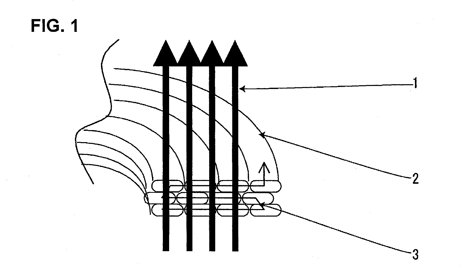
[0011]There are many types of wiring methods. One of such methods is an edgewise winding wire system in which the winding wires are wound around in the radial direction of the coil, and as shown in FIG. 1, since the interlinked area of the electric wires 2 and the magnetic flux 1 in the orthogonal direction is wide, according to which the stray loss within the winding 2 is increased, leading to the increase of winding loss and the rising of temperature accompanying the same. However, since the edgewise winding wire has a large radial area, it is strong against electromagnetic mechanical force in the radial direction generated during short circuit, and thus, it can be effectively applied to large-capacity models. However, as the capacity of the transformer increases, the amount of used wire increases and thus the stray loss increases. Further, since the mass per single winding wire is increased, when an edgewise winding wire not having any supplementary insulation member between layers is adopted in a transformer with only a single winding wire, the possibility of insulation breakdown is high, by which the coating of the electric wire may be damaged. Therefore, it is necessary to rid the potentials of increase of stray loss and damage of wire coating.
[0012]In order to cut down stray loss, it is necessary to downsize the electric wire so as to minimize the cross-sectional area interlinked with magnetic flux. The adopting of a cylindrical winding wire in which the electric wire can be minimized or the changing of electric wire dimension of the edgewise winding wire is considered. The cylindrical winding wire has a small radial direction wire dimension, so it is weak against electromagnetic mechanical force in the radial direction during short circuit. The electromagnetic mechanical force increases along with the increase of capacity, so that it is difficult to adopt cylindrical winding wires. When the wire dimension of the edgewise winding wire is changed, the cross-sectional area of the electric wire is increased, according to which the transformer is increased in size and the manufacturing costs are increased.
[0013]Therefore, the present invention aims at providing a transformer having a large capacity, capable of adopting an edgewise winding wire without increasing the electric wire dimension.
[0019]The present invention provides a coil transformer capable of reducing stray loss and cutting down increase of temperature, according to which the transformer can be downsized since there is no need to ensure a large electric wire cross-sectional area. Further, since the coil mass can be reduced, it becomes possible to rid the potentials of insulation breakdown caused by the damaging of the electric wire coating.

Problems solved by technology

However, as the capacity of the transformer increases, the amount of used wire increases and thus the stray loss increases.
Further, since the mass per single winding wire is increased, when an edgewise winding wire not having any supplementary insulation member between layers is adopted in a transformer with only a single winding wire, the possibility of insulation breakdown is high, by which the coating of the electric wire may be damaged.
The electromagnetic mechanical force increases along with the increase of capacity, so that it is difficult to adopt cylindrical winding wires.
When the wire dimension of the edgewise winding wire is changed, the cross-sectional area of the electric wire is increased, according to which the transformer is increased in size and the manufacturing costs are increased.

Method used


Image

  • Coil transformer composed of unit configuration
  • Coil transformer composed of unit configuration
  • Coil transformer composed of unit configuration

Examples


embodiment 1

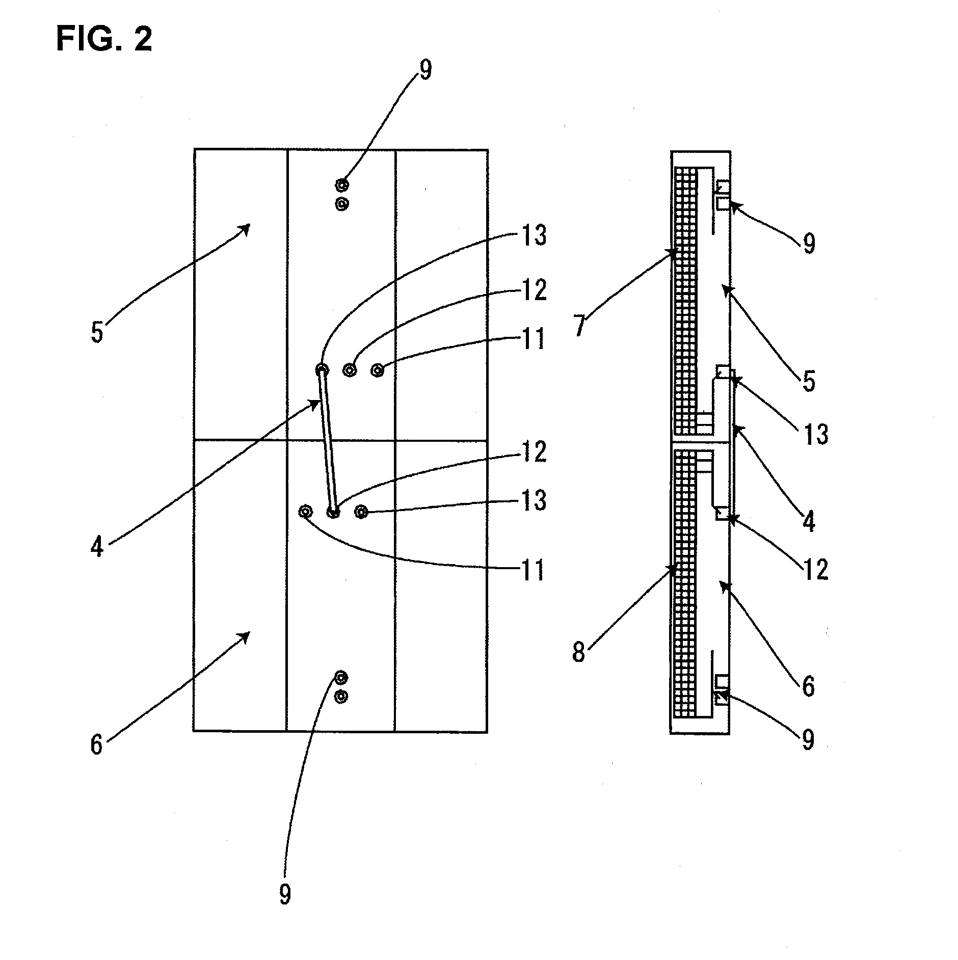
[0026]Two mold coil units (5 and 6) having a total number of windings N divided into N / 2 windings (=n windings) are formed. The structures of the two coil units 5 and 6 are the same. In other words, each coil has n windings, and the coil unit is equipped with a winding start terminal 9 and a winding end terminal 11 (n windings).

[0027]Although the actual state of connection is not illustrated, an end face of the side of the winding end terminal 11 of the No. 1 coil unit 5 is opposed and attached to an end face of the side of the winding end terminal 11 of the No. 2 coil unit 6, wherein the winding end terminal 11 of the No. 1 coil unit 5 (n windings) and the winding end terminal 11 of the No. 2 coil unit 6 (n windings) are drawn out to an external connection section and connected via external coupling terminals. Thus, a series (continuous) connection is realized and the total number of windings will be a maximum of (2n=N) windings.

[0028]Since this connection is a series connection, t...

embodiment 2

[0029]Two mold coil units (5 and 6) having a total number of windings N divided into N / 2 windings (=n windings) are formed. The structures of the two coil units 5 and 6 are the same. In other words, each coil has n windings, and the coil unit is equipped with a winding start terminal 9 and a winding end terminal 11 (n windings). In the proximity of the winding end terminal 11 (n windings) are disposed tap draw-out terminals 12 (n−a windings) and 13 (n−b windings) having somewhat smaller numbers of windings. In the embodiment, for example, n equals 300, a equals 15 and b equals 30. As can be recognized from this embodiment, what is meant by “somewhat” according to the present invention is the difference in the number of windings equal to or smaller than approximately 10% of the n number of windings.

[0030]As shown in FIG. 2, an end face of the side having the winding end terminal 11 of the No. 1 coil unit 5 is opposed and attached to an end face of the side having the winding end term...

embodiment 3

[0032]Two mold units 5 and 6 are manufactured in which the total number of windings are n times. Each of the No. 1 coil unit 5 and No. 2 coil unit 6 has a tap. At this time, the upper side of the No. 1 coil unit 5 is the winding start side and the lower side thereof is the winding end side, wherein tap draw-out terminals 12, 13 and 14 are disposed close thereto. The No. 2 coil unit 6 is placed up-side down wherein the upper portion thereof is the winding end side, and tap draw-out terminals 12, 13 and 14 are disposed close thereto. By connecting the tap draw-out terminal 14 of the No. 1 coil unit 5 and the tap draw-out terminal 14 of the No. 2 coil unit 6, the tap switch can double as a parallel connection terminal.

[0033]At this time, by connecting the tap draw-out terminal 14 of the No. 1 coil unit 5 and the tap draw-out terminal 14 of the No. 2 coil unit 6 and outputting an inter-terminal connection 4, a parallel connection is realized. The current value can be reduced to half acc...


PUM


Abstract

There are many varieties of windings. Coils adopting an edgewise winding wire in which winding wires are wound around in the radial direction of the coil have a wide flux linkage area orthogonal to the electric wire, so that stray loss within the wire is increased, winding wire loss is increased and temperature is raised thereby. The present invention provides an arrangement in which a plurality of coil units are prepared and connected via external coupling terminals. At this time, winding is performed so that the contact faces of the coil units have equal potentials, so that there is no need to ensure an insulation distance between coils, and the coils can be downsized. Therefore, the mass of the respective coils can be reduced. Taps disposed on the respective coils are arranged to have equal potentials, according to which the external coupling terminals can double as tap switch terminals, so that there is no need to provide a dedicated tap switch.

Description

[0001]The present application is based on and claims priority of Japanese patent application No. 2010-072455 filed on Mar. 26, 2010, the entire contents of which are hereby incorporated by reference.BACKGROUND OF THE INVENTION[0002]1. Field of the Invention[0003]The present invention relates to a coil transformer composed of a unit configuration. More specifically, the present invention provides a plurality of (n number of) coil units, wherein external coupling terminals of the coil units are mutually connected to configure a transformer having a desired capacity.[0004]2. Description of the Related Art[0005]Conventionally, companies were able to perform energy administration per factory or per business office. However, due to the revision of the Rationalization in Japanese Energy Use Law, companies using a total energy of 1500 kl or higher in a year as a whole entity are now required to report to the government the amount of used energy and be designated as specified entities. In ad...

Claims


Application Information

Patent Timeline
IPC IPC(8): H01F27/29
CPCH01F27/08H01F27/30H01F27/29H01F27/2823H01F29/02
Inventor TAKEUCHI, MASAKISUZUKI, ATSUSHIAZEGAMI, TATSUHITO
Owner HITACHI IND EQUIP SYST CO LTD
Learn More