
Non-woven reinforcement magnetic slot wedge

A technology of magnetic slot wedges and non-woven fabrics, which is applied in the direction of electrical components, electromechanical devices, windings, etc., can solve the problems of reducing generator efficiency, increasing generator temperature rise, and decreasing generator efficiency, so as to reduce stator leakage flux The effect of increasing and enhancing the longitudinal bending strength and reducing the amplitude of air gap harmonics

Inactive Publication Date: 2018-01-05
HARBIN ELECTRIC MASCH CO LTD
View PDF4 Cites 1 Cited by
  • Summary
  • Abstract
  • Description
  • Claims
  • Application Information

AI Technical Summary

Problems solved by technology

[0002] The stator core of the generator needs to be slotted to inlay the stator winding. Due to the difference in magnetic permeability, the distribution of the air gap magnetic field changes, forming a pulsating component distributed along the air gap, and eddy current loss is generated on the surface of the generator rotor, which is a stray loss of the generator. The main component of the generator; this phenomenon not only produces loss, reduces the efficiency of the generator, but also overheats the rotor surface, increases the temperature rise of the generator, affects the output of the generator and the insulation life; the loss caused by the pulsating component is related to the rated speed of the generator, The number of stator slots, air gap size and other factors are related, and these key parameters are often determined by the overall design of the generator and are related to the technical parameters of the generator. For some designs, such as the design of large turbogenerators, especially the number of stator slots Fewer electromagnetic schemes often produce such a contradiction: the loss of the pulsating component exceeds expectations, which reduces the efficiency of the generator; and the technical scheme of increasing the number of stator slots or increasing the size of the air gap can reduce the loss of the pulsating component. But it increases the manufacturing cost or increases the excitation loss, and also changes the performance parameters of the generator
[0003] In response to this problem, magnetic slot wedges are often used to solve this problem on small and medium-sized motors. Magnetic slot wedges can increase the magnetic permeability of the stator notch to reduce the amplitude of the air gap pulsation component, that is, to reduce the loss caused by the pulsation component. ; but this technology also has shortcomings: First, although the magnetic slot wedge can reduce the amplitude of the air gap pulsation component, it also increases the leakage flux component, which brings loss and reduces the performance of the motor. A trade-off must be made in the magnetic permeability of the slot wedge This problem, otherwise it is difficult to achieve the desired effect; on the other hand, the structural design, material selection and manufacturing technology of slot wedges are not mature, such as molded magnetic slot wedges, slot wedges processed by magnetic laminates, induced magnetic slot wedges, and magnetic putty slot wedges. etc., the actual performance cannot reach the expected effect, and the magnetic slot wedge is subjected to the alternating stress of the rotor magnetic pull, causing fatigue problems, often falling off and damaged, resulting in operational accidents; especially in large turbogenerators, the magnetic The problem of tension is more prominent, so that the magnetic slot wedge technology is still not applied; although the electromagnetic load of large turbogenerators is very high, the structure is compact, and the ventilation and cooling are limited, reducing stray losses is particularly important for improving the performance of the generator. However, reliability and other issues limit the application of magnetic slot wedge technology, making it difficult to break through the technology of reducing stray losses in large turbogenerators

Method used


Image

  • Non-woven reinforcement magnetic slot wedge
  • Non-woven reinforcement magnetic slot wedge
  • Non-woven reinforcement magnetic slot wedge

Examples


specific Embodiment approach

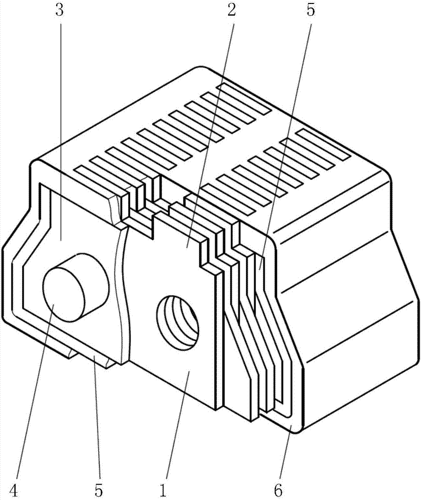
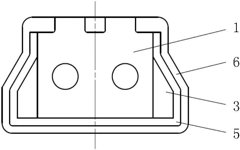
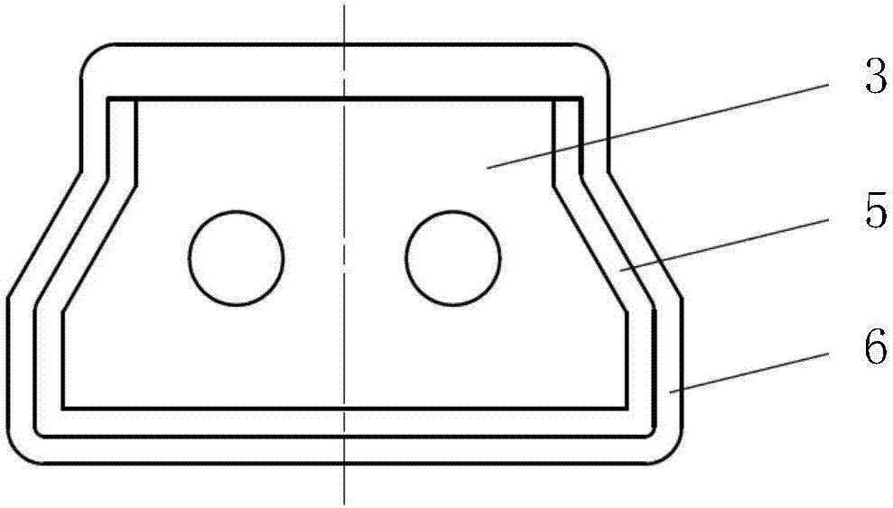
[0014] Specific embodiment: a kind of non-woven reinforced magnetic slot wedge, such as figure 1 , figure 2 , image 3 As shown, the magnetically conductive main body of the slot wedge is formed by stacking the magnetically conductive sheets 1; the magnetically conductive sheet 1 is punched from a silicon steel sheet, and has a rectangular structure with a width smaller than the slot width and a height smaller than the thickness of the slot wedge, and the upper end is exposed to the slot The flange 2 on the wedge top surface has a non-woven fabric pad 3 between adjacent magnetic conductive sheets 1. The non-woven fabric pad 3 is made of carbon fiber non-woven fabric, glass fiber non-woven fabric or other high-strength fiber cloth. The shape is the same as the section of the slot wedge, but the external dimension is smaller than the section of the slot wedge. The magnetic conductive sheet 1 and the non-woven fabric liner 3 have punching holes with the same size and position, ...


PUM


Abstract

The invention discloses a non-woven reinforcement magnetic slot wedge. A sheet magnetic conductive unit can lower the eddy current loss of itself, the distribution of magnetic lines of force in a stator groove can be changed, so that the intensity of harmonic waves is lowered, the effect of lowering the loss of the harmonic waves is achieved, a non-woven reinforcement structure can meet a requirement for structural rigidity and intensity and a requirement for turbonator air gap electromagnetic force, and the purposes of lowering the stray loss and improving the efficiency of the turnonator, increasing the performance index of the tunonator, and improving the reliability are achieved.

Description

Technical field: [0001] The invention relates to a non-woven reinforced magnetic slot wedge. Background technique: [0002] The stator core of the generator needs to be slotted to inlay the stator winding. Due to the difference in magnetic permeability, the distribution of the air gap magnetic field changes, forming a pulsating component distributed along the air gap, and eddy current loss is generated on the surface of the generator rotor, which is a stray loss of the generator. The main component of the generator; this phenomenon not only produces loss, reduces the efficiency of the generator, but also overheats the rotor surface, increases the temperature rise of the generator, affects the output of the generator and the insulation life; the loss caused by the pulsating component is related to the rated speed of the generator, The number of stator slots, air gap size and other factors are related, and these key parameters are often determined by the overall design of the ...

Claims


Application Information

Patent Timeline
Patent Type & Authority Applications(China)
IPC IPC(8): H02K3/493
Inventor 于鸿浩梁洪涛赵永昌胡刚李金香丁大鹏李士龙白洁刘平超
Owner HARBIN ELECTRIC MASCH CO LTD
Learn More