
Bar armor system for protecting against rocket-propelled grenades

a technology of rocket-propelled grenades and armor systems, which is applied in the field of bar armor systems, can solve the problems of reducing the protection afforded by these systems, unable to prevent the detonation of rpgs, and cumbersome rpg standoff armor systems, and achieves the effects of preventing the translation of vertical bars, preventing the detonation of rpgs, and improving the geometry of rpg-shaped charge d

Inactive Publication Date: 2011-09-29
GENERAL ATOMICS
View PDF7 Cites 31 Cited by
  • Summary
  • Abstract
  • Description
  • Claims
  • Application Information

AI Technical Summary

Benefits of technology

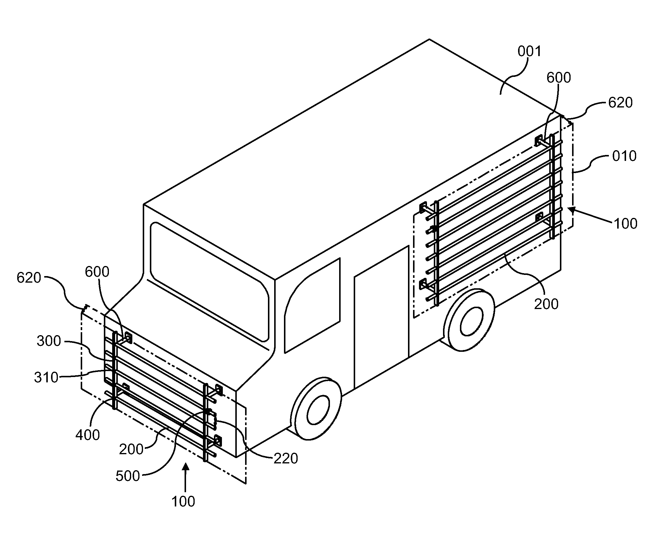
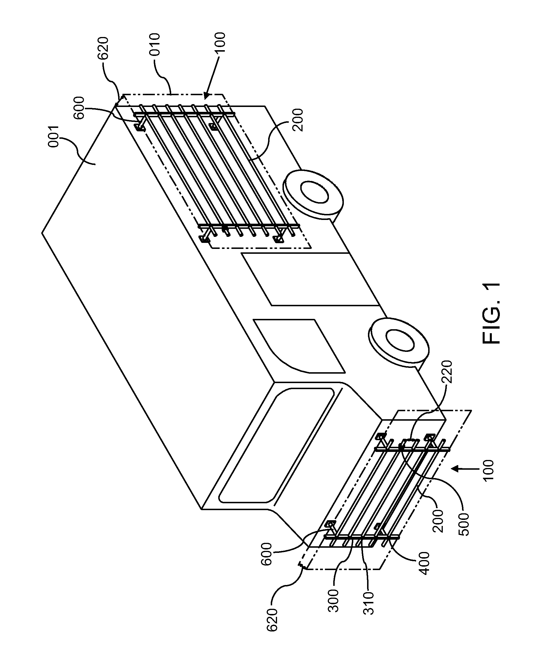
[0013]The lateral bars are approximately 5 / 16″ in diameter (which, for hexagonal cross-section lateral bars, is measured across the flats) and can be spaced apart at a distance less than about 57 mm for particular RPG threats. The hexagonal lateral bars are oriented having two flat faces oriented substantially vertically so as to provide a better geometry for reducing RPG shaped charge detonation. The bar arrays can further comprise at least two push washers disposed on at least one of the lateral bars abutting at least one of the vertical bars to prevent translation of the vertical bars. The mounts can comprise a bracket, which can further comprise a rotary latch, adapted to work in conjunction with particular lateral bars. The mounts can position the lateral bars at a distance of less than about 9 inches from the vehicle. The invention also provides bar armor that can be installed in kits, for easy installation, repair, and replacement. The system is also adapted to be electrostatically coated, including with a chemical agent resistant coating (“CARC”) to promote further efficiencies.

Problems solved by technology

These rudimentary standoff armor systems were cumbersome and not very successful.
The protection they attempted to afford was marginal at best.
No attempt was made in these systems to prevent the RPG from detonating or to cause the RPG to do as little damage as possible upon detonation.
This “slat armor” weighs approximately 5200 pounds and is quite cumbersome.
While these later designs have offered some improvement over the earlier rudimentary systems, they have not been entirely successful, and have even raised additional difficulties.
For example, although it is desirable to extend protection away from the vehicle, some of these systems appear to have extended the protection too far, resulting in increased size and weight and decreased maneuverability.
The increase to vehicle dimensions also makes the vehicle unnecessarily more visible in the field, thereby causing additional danger to the occupants.
These designs also have subjected the vehicle to increased wear and tear, and undue restriction in operations, such as in crowded urban environments, because of the increased size.
In addition, current systems also includes a lack of modularity in assembly and installation.
Such welding is difficult and time-consuming.
Additionally, when the welded designs break, a large portion of the bar or slat armor has to be replaced, rather than replacing only the damaged section.
This is expensive, time-consuming, and decreases the time that the protected vehicle is available for field use.
While not all previously-designed systems have employed welding, even the non-welded systems have not been satisfactory.
However, use of such parts can prevent a quick and efficient electrostatic coating and can instead require the use of wet paint, which is more expensive, less efficient, and more time-consuming.
Among the additional deficiencies in later designs is that they have not addressed the specific weapons sought to be defeated.
As a result, these designs do not adequately address the detonation details and capabilities of current weaponry and the dynamics of RPG impact.
Nor does it appear that earlier designs have given consideration to the dynamics and geometry of the bar armor systems themselves, and their components, to most effectively prevent formation of the most damaging explosions by RPGs.

Method used


Image

  • Bar armor system for protecting against rocket-propelled grenades
  • Bar armor system for protecting against rocket-propelled grenades
  • Bar armor system for protecting against rocket-propelled grenades

Examples


Embodiment Construction

[0022]The bar armor system of the present invention is adapted to minimize damage caused by rocket-propelled grenades (“RPGs”) by reducing the incidence of shaped charges forming upon contact or near-contact with a vehicle sought to be protected. Shaped charges are directionally-oriented explosive detonations (i.e., combustions that propagate via self-sustaining supersonic shock waves) that have the particular effect and highest incidence in causing damage. Shaped charges can be very damaging. Depending on the particular RPG, a shaped charge can penetrate at least 30 cm into armored steel or more. It is unacceptable to attempt to combat shaped charges by simply increasing the thickness of the vehicle armor. The increased thickness would make the vehicle so massive and cumbersome that it could effectively render the vehicle immobile.

[0023]The present invention reduces the need for increased armor thicknesses by substantially reducing the risk of shaped charges causing damage to a tar...


PUM


Abstract

A bar armor system is provided for reducing damage caused by RPGs launched towards a vehicle. The bar armor system includes at least one bar array, comprised of lateral bars and vertical bars, wherein the lateral bars are set in predetermined positions so as to reduce the possibility of shaped charges being directed towards the target vehicle. Tubular shaft retainers are provided to be positioned in annular openings in the vertical bars. The lateral bars can be of a round or hexagonal cross-section, and when hexagonal lateral bars are employed, the flat surfaces of the cross-section are positioned horizontally by the tubular shaft retainers so as to minimize the area presented to an oncoming RPG, particularly when the RPG strikes at a non-normal incidence. Push washers can be employed at the outside surfaces of the vertical bars so as to hold them in position. A mounting system is provided that is capable of positioning the bar armor system at close distances to the vehicle so that the overall size and weight of the vehicle is not unduly increased by the bar armor system. The mounts can include rotary latches to provide easy installation and removal. The system can also be of an electrically-conductive unified composition so that efficient electrostatic coating techniques can be used to cover the system. The system can also be provided in the form of kits for ready installation and for more economical repair.

Description

BACKGROUND OF THE INVENTION[0001]1. Field of the Invention[0002]This invention relates to bar armor. More particularly, this invention relates to bar armor systems for protecting a vehicle from rocket-propelled grenades.[0003]2. Description of Related Art[0004]Shortly after rocket-propelled grenades (“RPGs”) were used to attack vehicles, various forms of standoff armor arose to attempt to reduce the effectiveness of the RPGs. Towards the end of World War II, anti-vehicle infantry weapons came into wider use in response to the increasing use of tanks. To try to protect against these weapons, tank crews utilized a rudimentary form of standoff armor such as field-mounted bedsprings and / or screen doors positioned on the tank. Later, during the Vietnam War, additional forms of rudimentary standoff armor were employed, often comprised of scrap metal, screens, chicken wire, and chain-link fencing.[0005]These rudimentary standoff armor systems were cumbersome and not very successful. The pr...

Claims


Application Information

Patent Timeline
Patent Type & Authority Applications(United States)
IPC IPC(8): F41H7/00
CPCF41H5/013F41H5/026F41H5/023
Inventor KELLNER, JR., WILLIAM R.DICKSON, PAUL C.TRESTER, PAUL W.
Owner GENERAL ATOMICS
Learn More