
Optimization of microgrid energy use and distribution

a micro-grid and energy use technology, applied in the field of micro-grid technology, can solve the problems of not considering the relative cycling schedule of similarly situated homes along the same circuit, not optimizing the relative cycling of customers, and not tying the cycling directly, so as to optimize the energy use, energy consumption, and energy consumption. the effect of cost or cost, energy price and energy cos

Inactive Publication Date: 2011-09-22
INTEGRAL ANALYTICS
View PDF76 Cites 530 Cited by
  • Summary
  • Abstract
  • Description
  • Claims
  • Application Information

AI Technical Summary

Benefits of technology

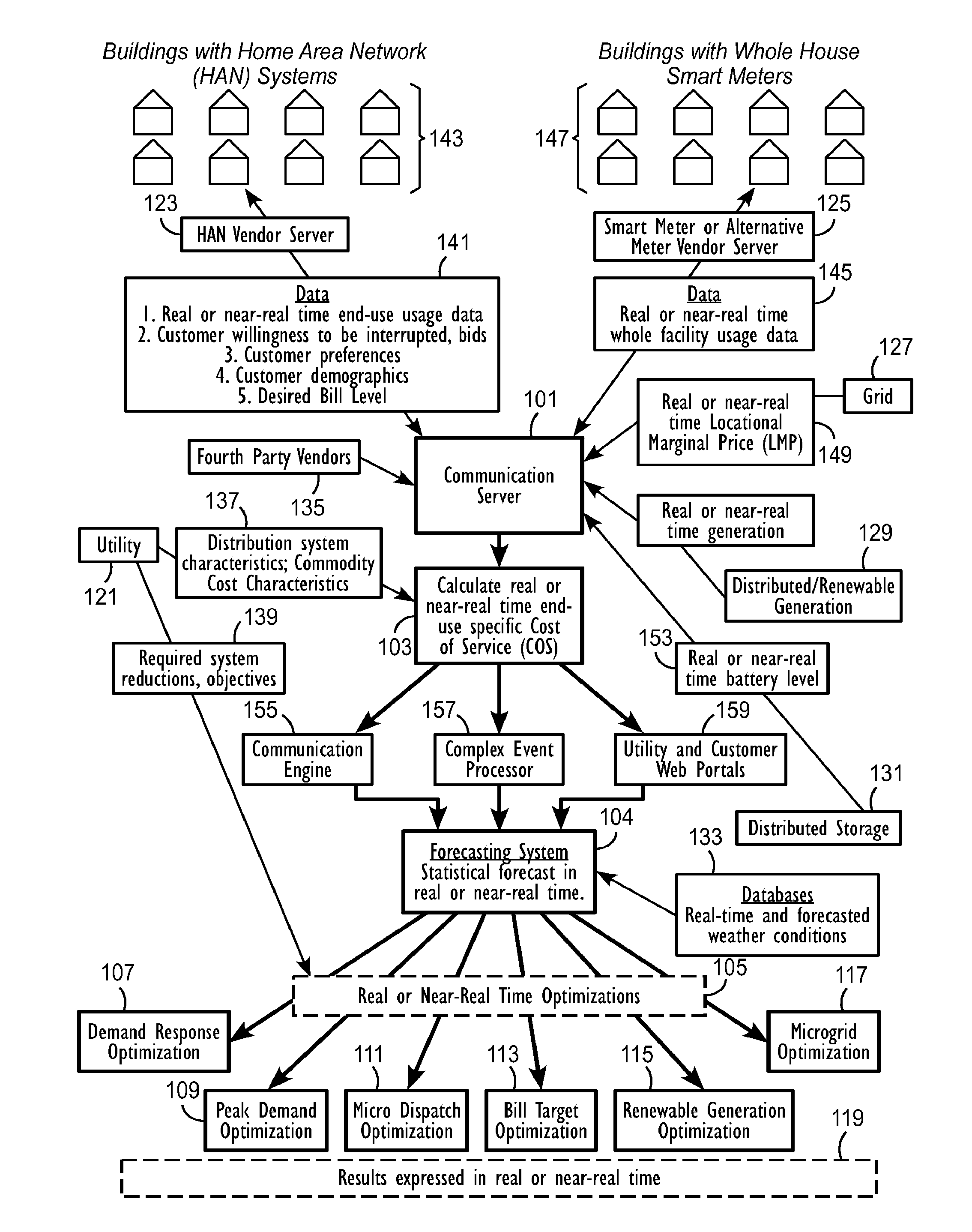
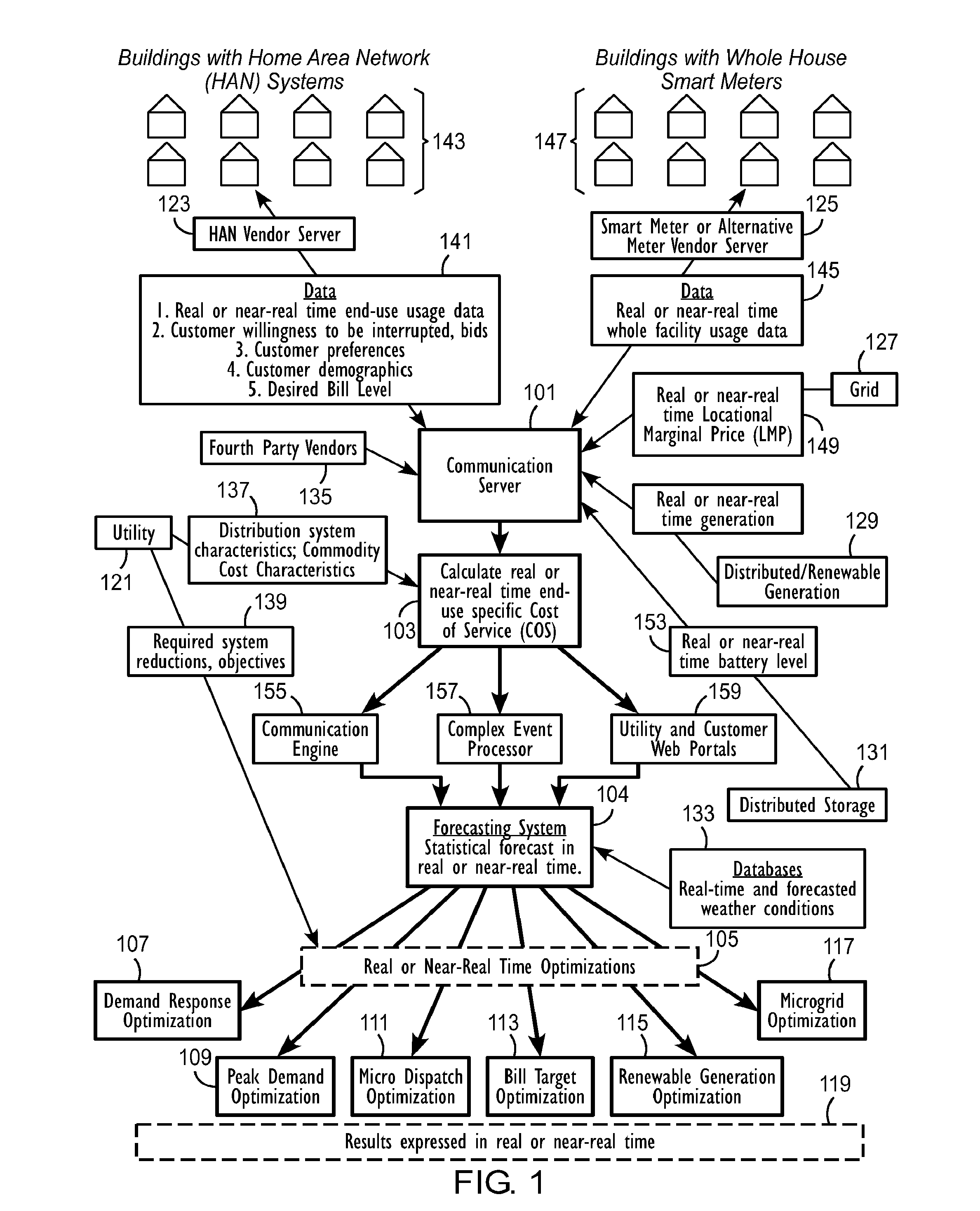
[0016]Certain embodiments of the present invention may provide a system for near real-time, micro level energy optimization. A system may include a server and one or more databases, the server operating in near real-time. The system may communicate with an energy provider that supplies energy to a plurality of customers to receive energy provider data, at least one information collector to receive information collector data including at least one of individualized energy usage data, customer preferences, and customer or location characteristics from the at least one information collector, and the one or more databases to receive data for optimization from the one or more databases. The system may calculate a cost of service or avoided cost for at least one of the plurality of customers or customer locations using at least one of the individualized energy usage data and a system generation cost at a nearest bus. The system may forecast at least one of individualized demand by end-use, or individualized demand by location for at least one of the plurality of customers or customer locations, or energy prices and energy costs. The system may also optimize energy distribution, energy use, the cost of service, or avoided cost using at least one of: the forecasted individualized demand by end-use, the forecasted individualized demand by location, the forecasted energy prices, and the forecasted energy costs. Interaction between the calculating, forecasting and optimizing may allow management and dispatch of end-uses and energy supply at a micro level in near real-time.

Problems solved by technology

The utility, however, would not consider the relative cycling schedules for similarly situated homes along the same circuit.
The utility would not optimize cycling of customers relative to one another along a circuit, nor tie the cycling directly to the intra-hour peak demand of the utility, the localized or customer-specific cost to serve, or the characteristics and avoided costs related to the customers' location on a circuit.
First, the forced change in an appliance's duty or “on” cycle, via traditional one way signaling, ignored the operations and scheduling of other appliance loads on a circuit.
Second, traditional supply dispatching decisions valued only the marginal cost changes caused by aggregate supply changes and aggregate demand reduction of one-way signaling.
Third, in the case of adding a supply side resource, energy still must be transmitted, distributed, and voltage adjusted in the delivery of electrons from a centralized plant to the customer's site.
Traditional supply-oriented dispatching systems do not consider, or incorporate, distribution level cost benefits or risks within their dispatching decisions.
Similarly, grid-based distribution management systems do not include supply side energy costs in their control systems which attend more toward voltage, reactive power, power factor, primary line losses or capacity inadequacies.
With the rapid development of smart grid technologies, consumers will likely be faced with time differentiated rates for energy and a bewildering array of dispatchable and smart appliances.

Method used


Image

  • Optimization of microgrid energy use and distribution
  • Optimization of microgrid energy use and distribution
  • Optimization of microgrid energy use and distribution

Examples


Embodiment Construction

[0133]The following systems and methods may provide reliable, least cost electricity to households and businesses.

[0134]Embodiments of the present invention may include several aspects. Embodiments may provide a process and method for jointly (1) forecasting, (2) optimizing and (3) costing the management and dispatch of ends uses and energy supply at a (4) micro level in (5) near real time. The confluence of these functions, when combined together and focused at a micro level energy application, in near real time, may provide significant cost savings and efficiencies beyond the traditional utility focus which tends to use aggregated loads, average or non-customer specific costs, and is not able to adjust end use demands in near real time. The micro level is preferably an end-use level, in contrast to a location level.

[0135]First, traditionally, electric energy providers have not managed energy using (1) forecasted loads within a home, at (4) the micro or end-use level. Rather, decis...


PUM


Abstract

Systems and methods for energy optimization may receive receiving energy provider data, near-real time individualized energy usage data for each of a plurality of end-uses or near-real time individualized whole premise energy usage data, customer preferences, and near-real time and forecasted weather information. The systems and methods may forecast, for a selected time period, individualized energy usage for each of the plurality of end-uses or individualized whole premise energy usage data for a customer location using: (1) the energy provider data, (2) the near-real time individualized energy usage data, (3) the customer preferences, and (4) the near-real time and forecasted weather information. The systems and methods may optimize, for the selected time period, energy usage at the customer location using (1) the individualized energy usage, (2) the energy provider data, and (3) the customer preferences.

Description

CROSS-REFERENCE TO RELATED APPLICATIONS[0001]This application claims priority to U.S. Provisional Patent Application No. 61 / 321,030, filed Apr. 5, 2010; the contents of which are incorporated by reference in their entirety. This application is a Continuation-in-part of U.S. patent application Ser. No. 12 / 915,870, filed Oct. 29, 2010, which is a Continuation of U.S. patent application Ser. No. 12 / 687,827, filed Jan. 14, 2010, which claims the benefit of U.S. Provisional Patent Application No. 61 / 144,642, filed Jan. 14, 2009, and U.S. Provisional Patent Application No. 61 / 228,010, filed Jul. 23, 2009; the contents of which are incorporated by reference herein in their entireties.FIELD OF THE INVENTION[0002]The present invention relates to microgrid technology, and, more specifically, to optimization of energy use and distribution within a microgrid system.BACKGROUND OF INVENTION[0003]The most common historical methods and processes for reducing peak electric demand involve controlling...

Claims


Application Information

Patent Timeline
Patent Type & Authority Applications(United States)
IPC IPC(8): G06F1/26
CPCG06Q10/06H02J3/008Y02B70/3225Y04S20/222Y04S50/10G06Q50/06H02J2310/64H02J3/003H02J2310/10H02J3/14Y02A30/00
Inventor OZOG, MICHAEL T.
Owner INTEGRAL ANALYTICS
Learn More