
Gas turbine with external combustion, applying a rotating regenerating heat exchanger

Inactive Publication Date: 2011-09-22
ARES TURBINE
View PDF12 Cites 73 Cited by
  • Summary
  • Abstract
  • Description
  • Claims
  • Application Information

AI Technical Summary

Benefits of technology

[0008]A second object of the present invention is to enhance the energy conversion, reducing the requirement for down time due to repair, maintenance and cleaning of the various parts of the turbine system, including the heat exchanger.
[0031]An additional advantage according to the present invention is that the heat exchanger may be more or less continuous cleaned in a manner removing possible carbon deposits or ash deposits on the heat exchanging surfaces of the regenerative heat exchanger without having to close down the plant.

Problems solved by technology

Apart from the fact that such plants are large and complicated with respect to energy output, said solutions are well functioning solutions.

Method used


Image

  • Gas turbine with external combustion, applying a rotating regenerating heat exchanger
  • Gas turbine with external combustion, applying a rotating regenerating heat exchanger
  • Gas turbine with external combustion, applying a rotating regenerating heat exchanger

Examples


Embodiment Construction

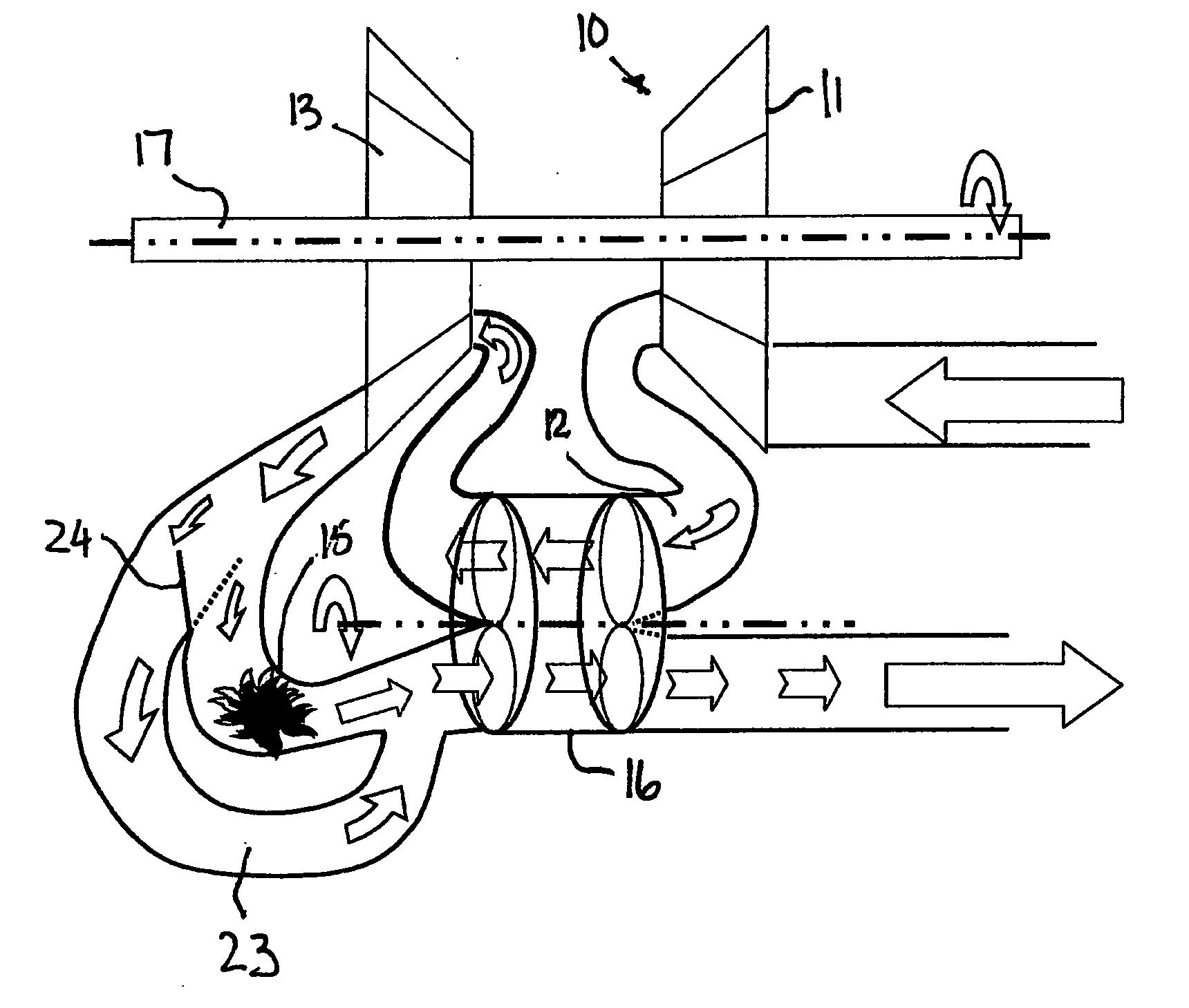
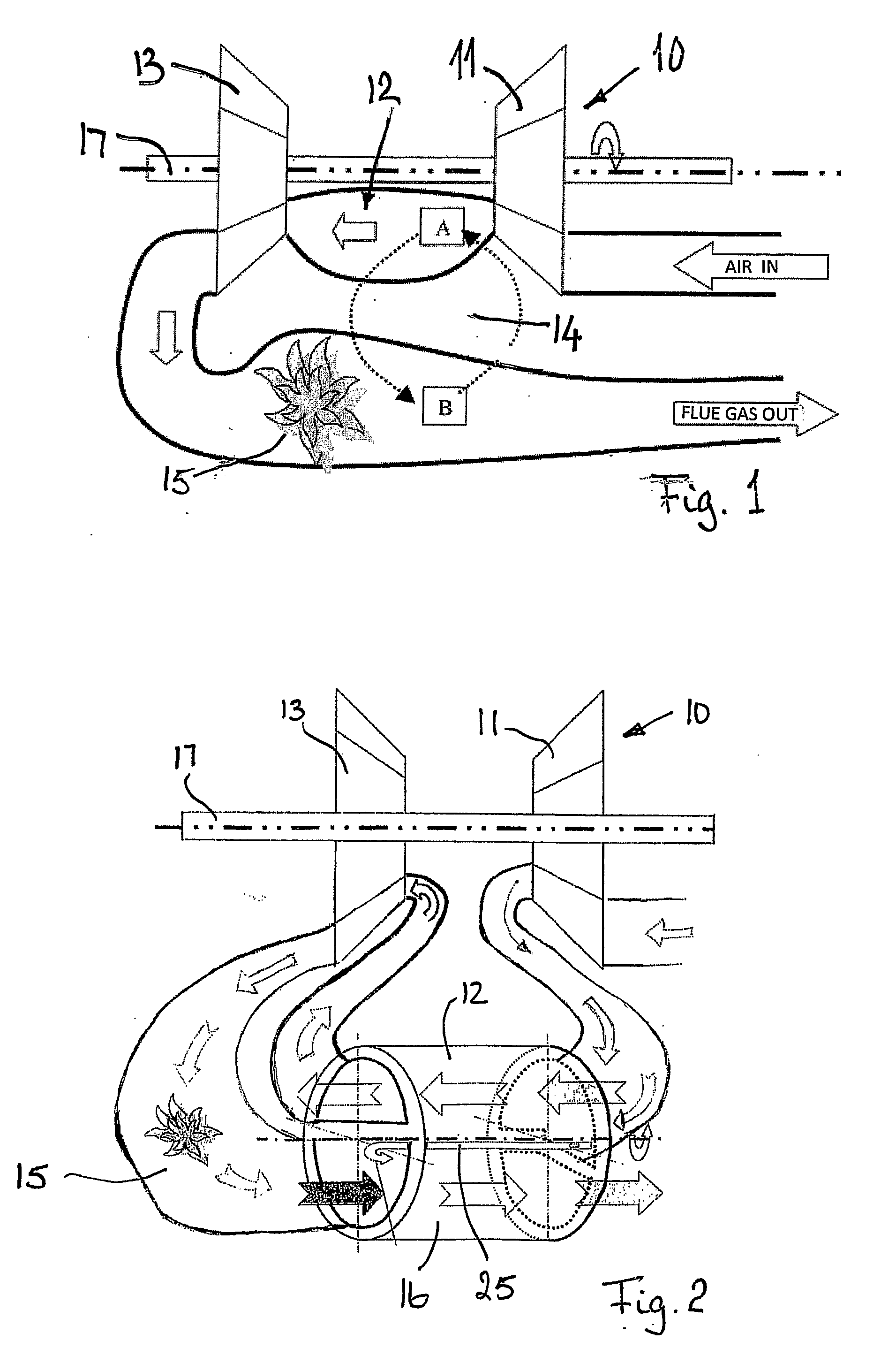
[0042]FIG. 1 shows schematically and very simplified a sketch of the principle applied according to the present invention. A gas turbine 10 comprises a compressor unit 11 employed for compressing air from a pressure p1 of 1 bar to a pressure p2 of 2 bar, while the temperature as a consequence of the compression is increased from T1=20° C. to a temperature of T2=200° C. Across the compressor unit the air velocity is increased from v1=1 m3 / sec to a velocity of v2=0.86 m3 / sec. In the compression chamber 12 between the compressor unit 11 and the turbine unit 13 of the turbine 10, the compressed gas is heated further by means of a regenerative heat exchanger 14 to a temperature of T2=800° C. while the pressure is maintained at a pressure of p3=2 bar. The velocity of the air is due to the heating increased to v3=1.83 m3 / sec. Then, the compressed and heated gas is directed to the turbine unit 13 where the air is expanded to a pressure of p4=1 bar and where the temperature is reduced to T4=...


PUM


Abstract

The invention relates to a gas turbine (10) for transforming thermal energy, for example from coal, biomass or the like, to mechanical work, comprising a compressor unit (11), a turbine unit (13, a combustion chamber (15) and a heat exchanger (14) with associated pipe system. The gas turbine (10) id configured in such way that the heat is supplied to the air flow between the compressor unit (11) and the turbine unit (13) by means of hot flue gas from the combustion chamber (15) and is brought into a compression chamber (12) arranged between the compressor unit (11) and the turbine unit (13).

Description

TECHNICAL FIELD OF THE INVENTION[0001]The present invention relates to a process and a plant for utilizing solid or particulate fuel as an energy source for gas turbines without first having to produce steam for producing work by using for example waste burning, coal combustion or burning pellets or the like.BACKGROUND FOR THE INVENTION[0002]During recent years, technical solutions for transferring thermal energy into mechanical work have been proposed many. Since oil up to now has been relatively cheap, research and development have in general been focused on developing heat power machines using oil as an energy source. The situation of to-day is that the oil price is much higher than for example bio mass energy.[0003]Several solutions for converting thermal energy from coal, bio energy and the like into mechanical work have been proposed. The proposed solutions propose to use steam powering turbines. Apart from the fact that such plants are large and complicated with respect to en...

Claims


Application Information

Patent Timeline
IPC IPC(8): F02C6/04H02K7/18
CPCF02C1/04F02C7/10F02C7/08F02C3/14F05D2220/60F02C7/105F28D19/042F05D2220/75F05D2220/768F05D2260/606
Inventor KLENVEN, OLE BJORN
Owner ARES TURBINE
Learn More