Steering lock device

a technology of locking device and lock body, which is applied in the direction of mechanical control device, keyhole guard, instruments, etc., can solve the problems of increasing costs and achieve the effect of increasing costs

Inactive Publication Date: 2011-09-22
ALPHA
View PDF19 Cites 0 Cited by
  • Summary
  • Abstract
  • Description
  • Claims
  • Application Information

AI Technical Summary

Benefits of technology

[0006]However, in the conventional key device 100, it is required to attach the pin 108 to the le...

Problems solved by technology

However, in the conventional key device 100, it is required to attach the pin 108 to the lever...

Method used


Image

  • Steering lock device
  • Steering lock device
  • Steering lock device

Examples


Embodiment Construction

)

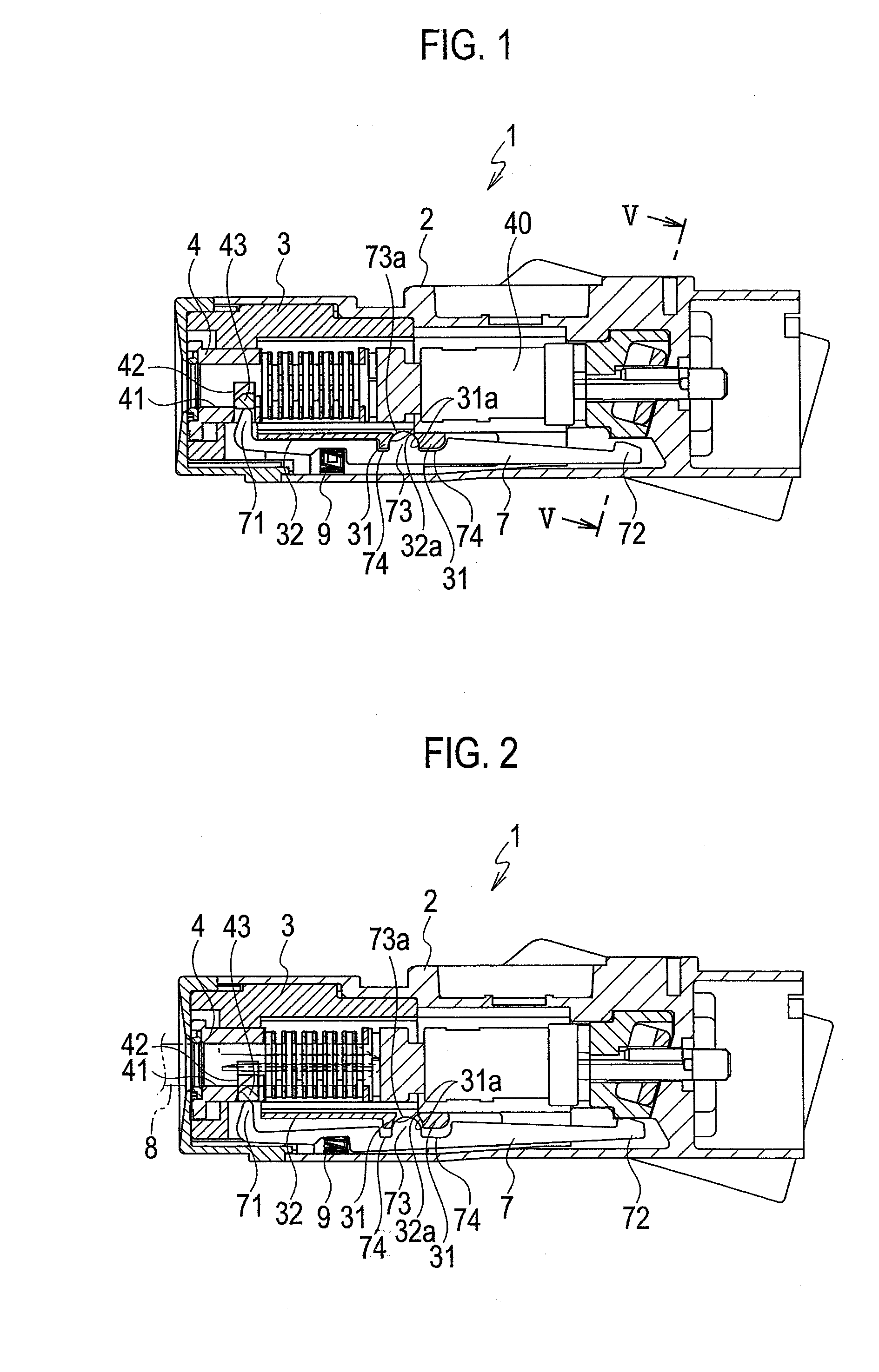
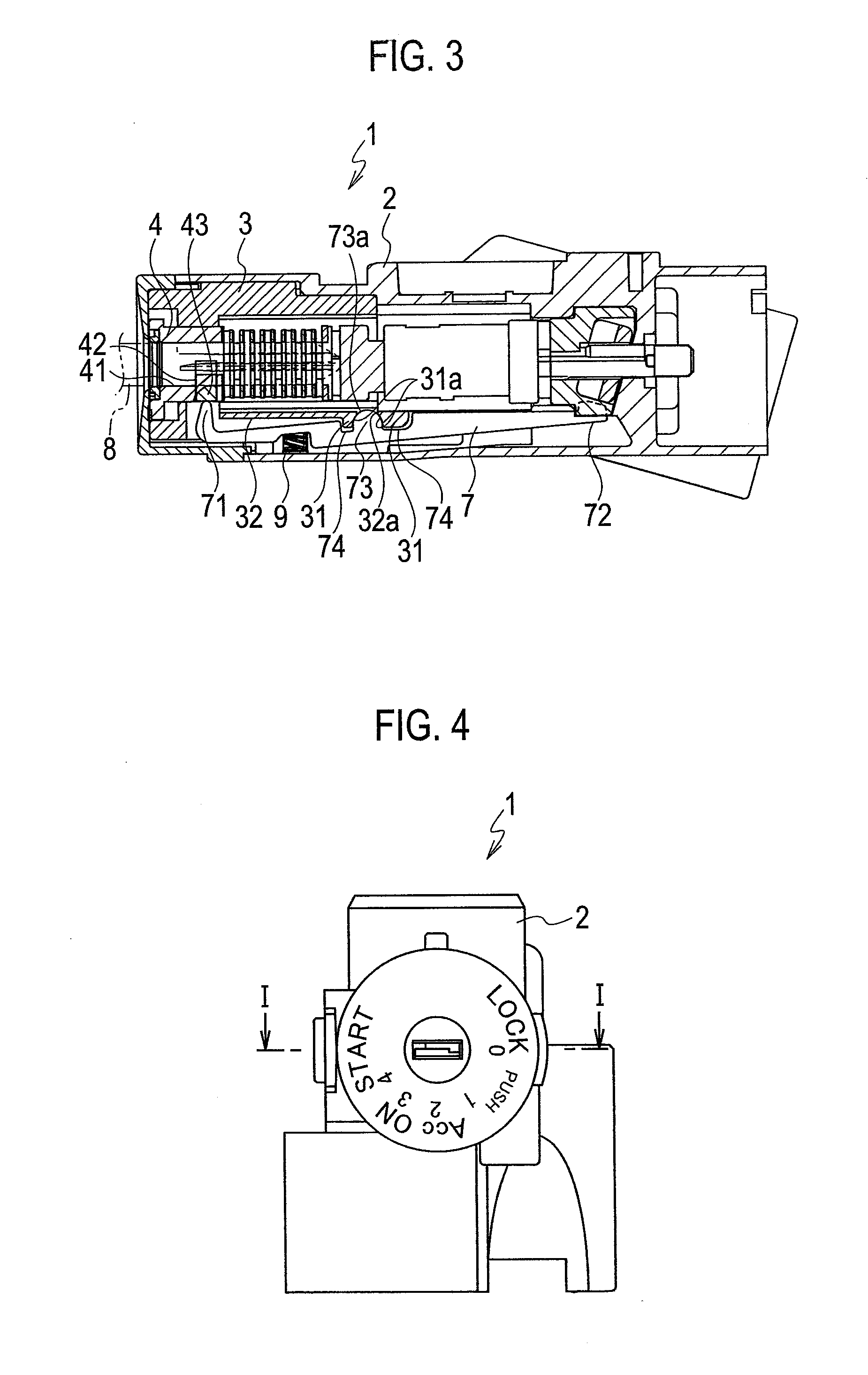
[0023]Hereinafter, an embodiment according to the present invention will be explained with reference to FIG. 1 to FIG. 6. Note that FIG. 1 is a cross-sectional view taken along a line I-I shown in FIG. 4.

[0024]As shown in FIG. 1 to FIG. 3, the steering lock device 1 according to the present embodiment includes a housing 2, a key cylinder 3, a key rotor 4, a rotator 40, a cam member 5 (see FIG. 5), a lock member 6 (see FIG. 5), and a lever 7. The key cylinder 3 is housed in the housing 2. The key rotor 4 is rotatably provided in the key cylinder 3. The rotator 40 is coupled with the key rotor 4 to rotate along with the key rotor 4. As shown in FIG. 5, an interlock hole 61 that interlocks with the cam member 5 is formed on the lock member 6. In addition, an end of the lock member 6 projects from a bottom face of the housing 2 when locked to engage with a steering shaft (not shown), and is retracted in the housing when unlocked. The lever 7 is interposed between the housing 2 and the ...


PUM


Abstract

In a steering lock device, a lever extending along an axial direction of a key rotor is provided between a housing and a key cylinder. A pivot-point portion protruded toward the key cylinder is provided on the lever. The lever swings about the pivot-point portion as its swing center in a radial direction of the key cylinder in a state where the pivot-point portion contacts with a pivot-point receive portion on the key cylinder. Then the lever is displaced in the radial direction of the key rotor with its end portion as its pivot point. According to the steering lock device, a pin as a swing center is not required, and locking/unlocking the lock member can be controlled by the lever along with insertion/removal of the key.

Description

CROSS-REFERENCE TO RELATED APPLICATIONS[0001]This is a National Phase Application filed under 35 U.S.C. §371 as a national stage of PCT / JP2009 / 068794, filed on Nov. 4, 2009, an application claiming the benefit under 35 U.S.C. §119 of Japanese Patent Application No. 2008-302346, filed on Nov. 27, 2008, the content of each of which is hereby incorporated by reference in its entirety.TECHNICAL FIELD[0002]The present invention relates to a steering lock device that locks rotation of a steering shaft of an automobile.BACKGROUND ART[0003]As a conventional steering lock device, a key device disclosed in Japanese Granted Patent Publication No. 2752709 is known. The key device includes a key cylinder 101, a key rotor 104, a slider 106, a lever 107, a pin 108 and a spring 109, as shown in FIG. 7. The key rotor 104 is rotatably provided in the key cylinder 101. An insertion hole 102 and a guide slit 103 are formed on the key rotor 104. The slider 106 is movably provided in the guide slit 103, ...

Claims


Application Information

Patent Timeline
IPC IPC(8): B60R25/02B60R25/021
CPCB60R25/02Y10T70/5765B60R25/021B60R25/02115B60Y2304/05B62D1/184
Inventor KURATA, TAKEBUMI
Owner ALPHA
Why Eureka
Try Eureka