
Multi-core optical fiber

a multi-core, optical fiber technology, applied in the direction of optical fibres with multi-layer cores/claddings, optical waveguide light guides, instruments, etc., can solve the problems of multi-core optical fibers that are not sufficiently examined for reducing transmission losses and nonlinearity, multi-core optical fibers have problems, etc., to reduce crosstalk between adjacent cores, reduce the loss of light propagating in the plural core, and reduce the effect of multi-core optical fibers

Inactive Publication Date: 2011-09-15
SUMITOMO ELECTRIC IND LTD
View PDF7 Cites 47 Cited by
  • Summary
  • Abstract
  • Description
  • Claims
  • Application Information

AI Technical Summary

Benefits of technology

[0011]The present invention has been developed to eliminate the problems described above. It is an object of the present invention to provide a multi-core optical fiber in which transmission loss and nonlinearity are reduced.
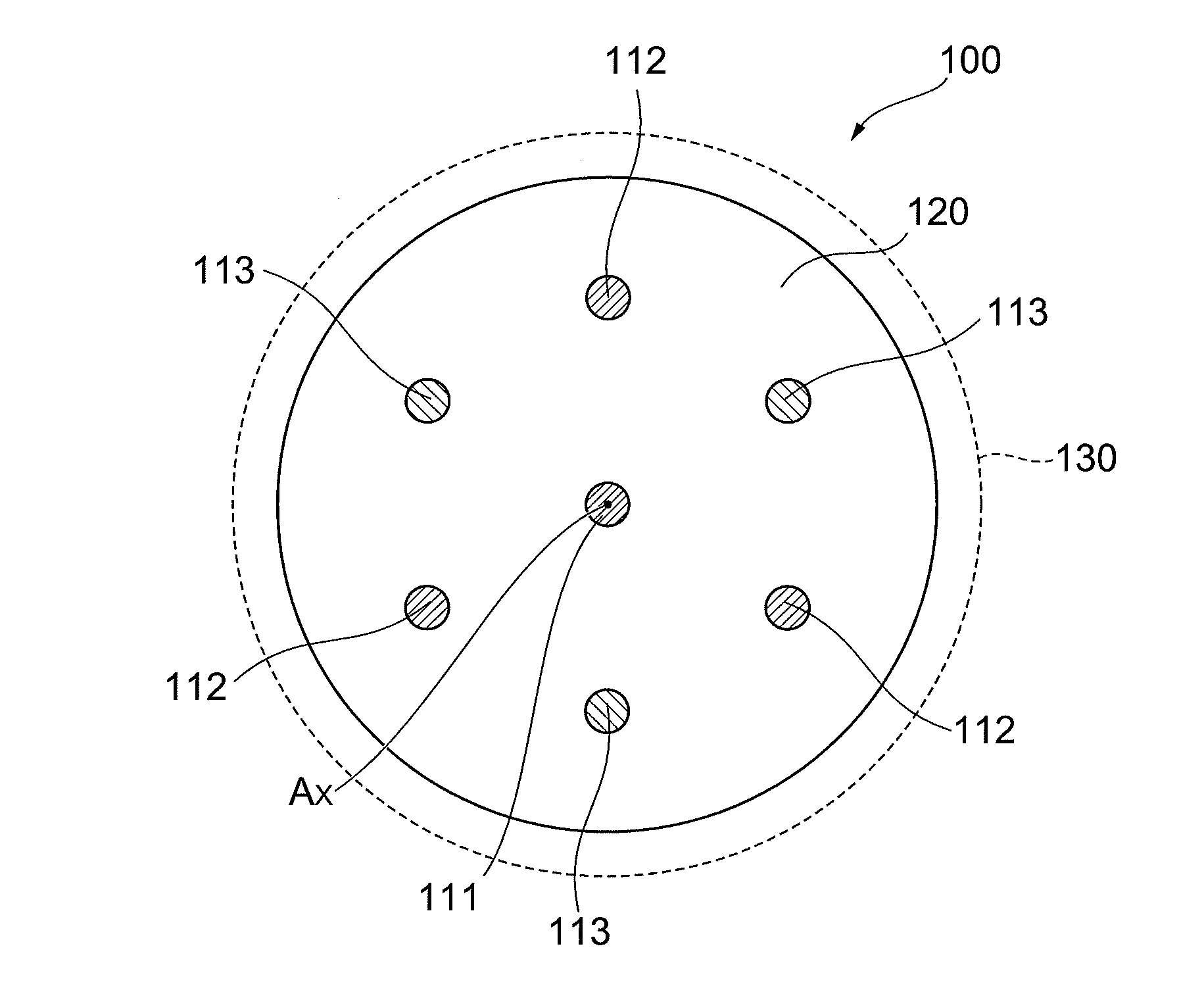
[0013]In accordance with the multi-core optical fiber having such a structure described above, the plural cores each comprised of silica glass doped with chlorine or pure silica glass are arranged in the cladding comprised of silica glass doped with fluorine, whereby transmission loss and nonlinearity of light propagating in the plural cores of the multi-core optical fiber are reduced.
[0014]Here, the amount of doped chlorine may be different between cores arranged so as to be adjacent to each other among the plural cores. In this case, by employing an aspect in which the amount of doped chlorine may be different between cores adjacent to each other, it is possible to change the refractive index difference between adjacent cores arbitrarily. As a result, crosstalk between adjacent cores can be reduced.
[0017]Furthermore, the multi-core optical fiber according to the present invention may comprises one or more leakage reduction portions for reducing leakage light propagating from each of the cores to a periphery thereof. In this case, at least a part of each of the leakage reduction portions exists on a straight line connecting cores adjacent to each other among the plural cores. In this manner, by providing each of the leakage reduction portions arranged such that at least a part thereof is positioned between cores adjacent to each other, crosstalk due to leakage light from each of the cores can be reduced effectively without increasing transmission loss of the multi-core optical fiber.

Problems solved by technology

Namely, the multi-core optical fibers disclosed in Documents 1 and 2 are not sufficiently examined for reduction in transmission losses and nonlinearity.
Consequently, there is a possibility that the multi-core optical fibers have problems when applied to large-capacity and long-haul transmission.

Method used


Image

  • Multi-core optical fiber
  • Multi-core optical fiber
  • Multi-core optical fiber

Examples


first embodiment

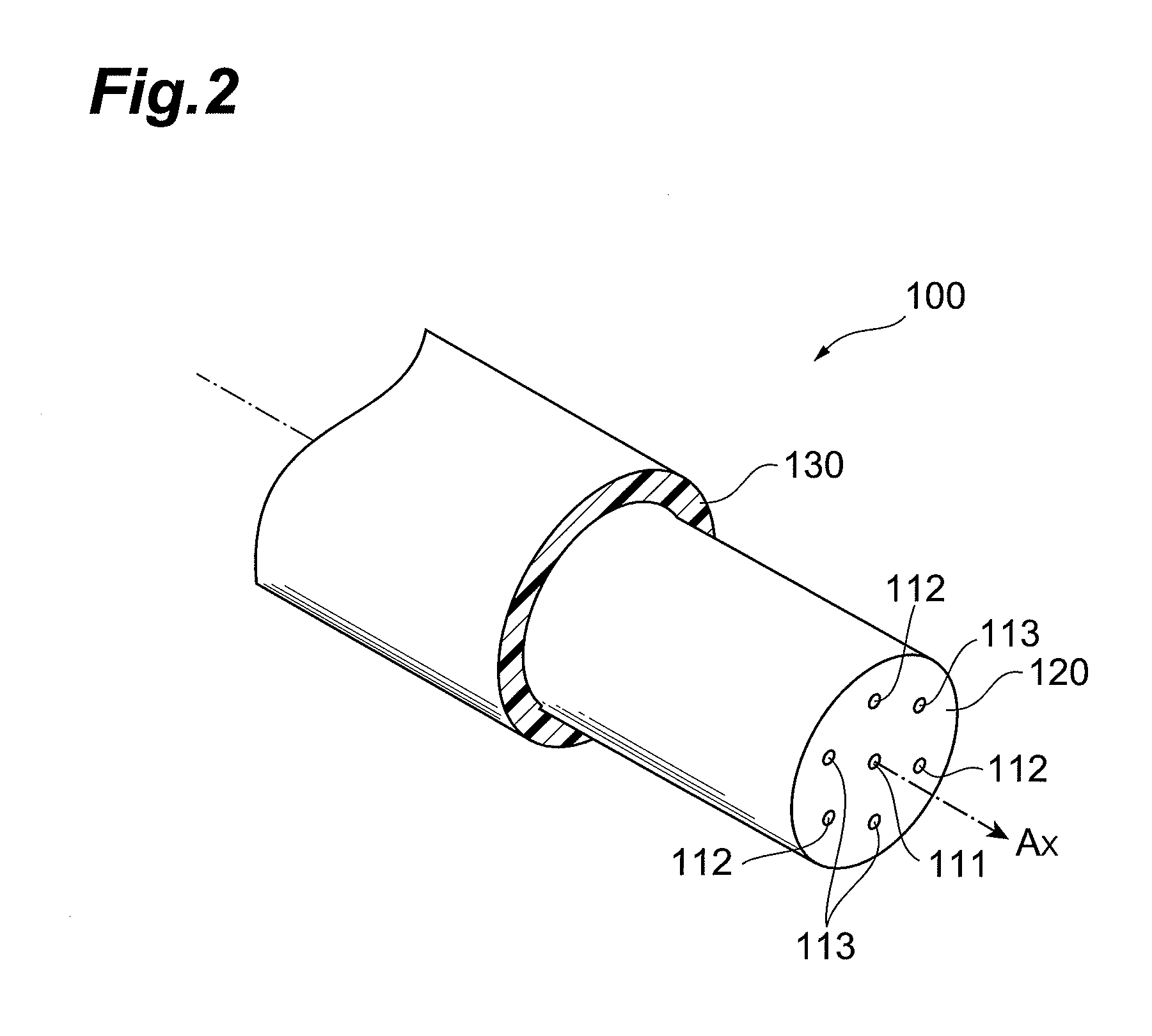
[0029]FIG. 2 is a view showing a schematic structure of a multi-core optical fiber according to a first embodiment of the present invention. FIG. 3 is a view showing a cross-sectional structure of the multi-core optical fiber according to the first embodiment. A multi-core optical fiber 100 shown in FIG. 2 is an optical fiber extending along a center axis Ax (a predetermined axis corresponding to a longitudinal direction of the multi-core optical fiber 100), and comprises plural cores 111 to 113, a cladding 120 surrounding the peripheries of the plural cores 111 to 113 and having a circular cross-section on a plane perpendicular to the center axis Ax, and a covering portion 130 provided on the outer periphery of the cladding 120. In the cladding 120, a center core 111 provided in the center of the cladding 120 and extending along the center axis Ax, and two types of peripheral cores 112 and 113 provided in positions different from that of the center core 111 and extending along the ...

second embodiment

[0035]FIG. 4 is a view showing a cross-sectional structure of a multi-core optical fiber according to a second embodiment of the present invention. A multi-core optical fiber 200 according to the second embodiment is different from the multi-core optical fiber 100 according to the first embodiment (FIG. 3) in the following point: the relative refractive index differences of the center core and the peripheral cores are the same, and the diameters of peripheral cores arranged adjacent to each other are different. In the same manner as in FIG. 3, a cross-section corresponding to a plane perpendicular to the center axis Ax of the multi-corer optical fiber 200 is shown in FIG. 4.

[0036]In particular, the multi-core optical fiber 200 according to the second embodiment comprises plural cores 114 to 116, the cladding 120 surrounding the peripheries of the plural cores 114 to 116, and a covering portion 230 provided on the outer periphery of the cladding 120. In the center of the cladding 120...


PUM

PropertyMeasurementUnit
diametersaaaaaaaaaa
diametersaaaaaaaaaa
diameteraaaaaaaaaa

Abstract

The present invention relates to a multi-core optical fiber having a structure for reducing transmission loss and nonlinearity. The multi-core optical fiber comprises plural cores extending along a center axis direction, and a cladding surrounding the peripheries of the plural cores. The cladding is comprised of silica glass doped with fluorine, and each of the plural cores is comprised of silica glass doped with chlorine or pure silica glass.

Description

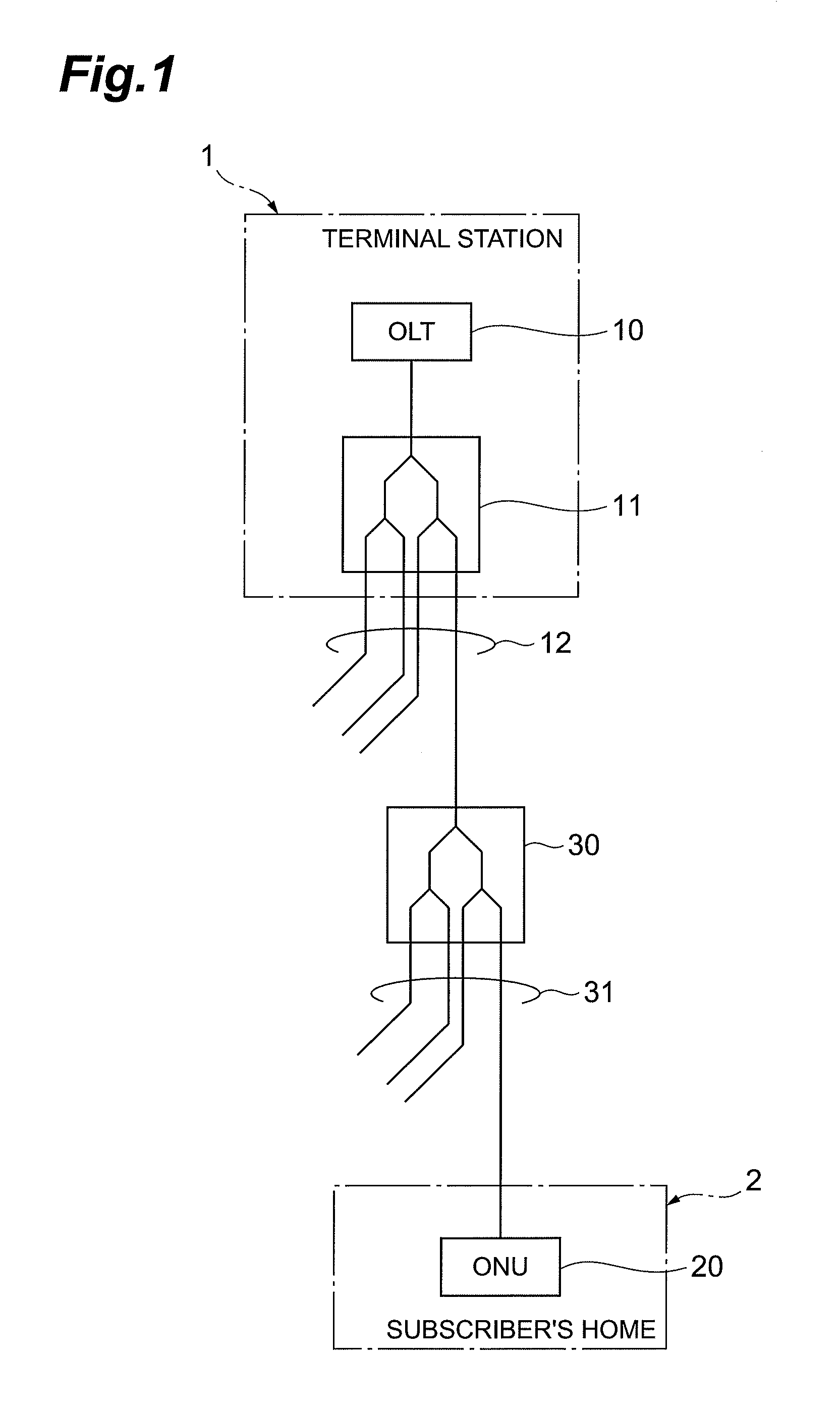
BACKGROUND OF THE INVENTION[0001]1. Field of the Invention[0002]The present invention relates to a multi-core optical fiber.[0003]2. Related Background Art[0004]Conventionally, to provide FTTH (Fiber To The Home) services that enable optical communications between a single transmitter station and plural subscribers, for example, as shown in FIG. 1, a so-called PON (Passive Optical Network) system in which subscribers share a single optical fiber by interposing a multistage optical splitter is realized.[0005]In other words, the PON system shown in FIG. 1 includes a terminal station 1 (transmitter station) that is a final relay station of an existing communication system such as the Internet, and an optical fiber network installed between the terminal station 1 and a subscriber's home 2 (subscriber). The optical fiber network is composed of a closure (including an optical splitter 30) provided as a branch point, an optical communication line 12 from the terminal station 1 to the closu...

Claims


Application Information

Patent Timeline
Patent Type & Authority Applications(United States)
IPC IPC(8): G02B6/036
CPCG02B6/0365G02B6/02042
Inventor SASAOKA, EISUKETARU, TOSHIKINAGASHIMA, TAKUJI
Owner SUMITOMO ELECTRIC IND LTD
Learn More