
Droplet manipulations on EWOD microelectrode array architecture

Inactive Publication Date: 2011-09-15
SPARKLE POWER
View PDF3 Cites 60 Cited by
  • Summary
  • Abstract
  • Description
  • Claims
  • Application Information

AI Technical Summary

Benefits of technology

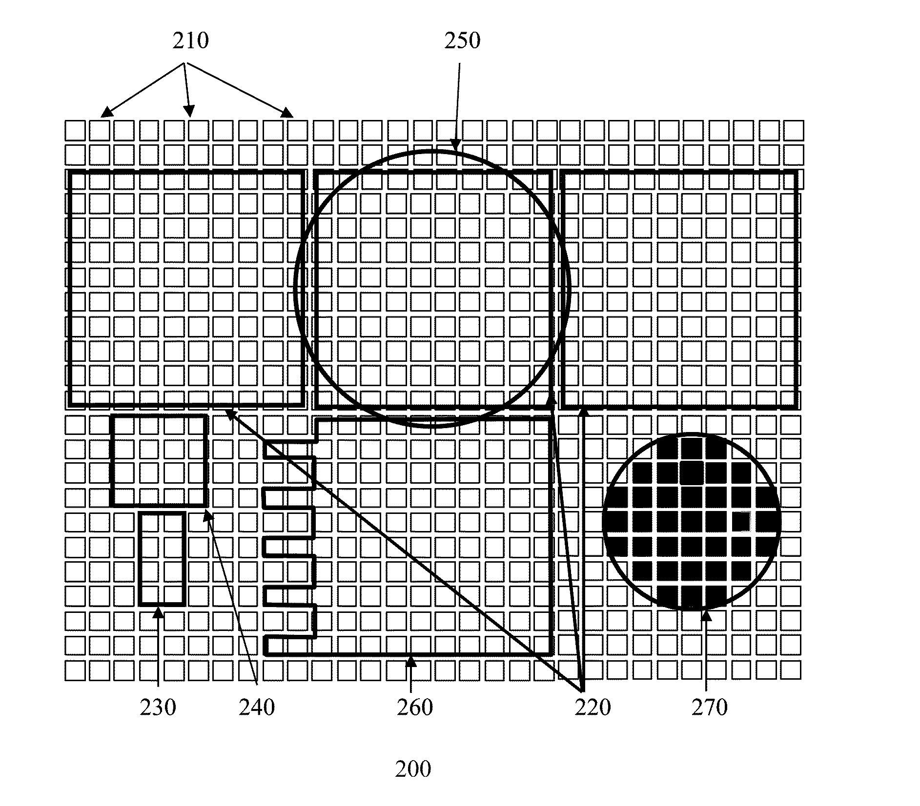
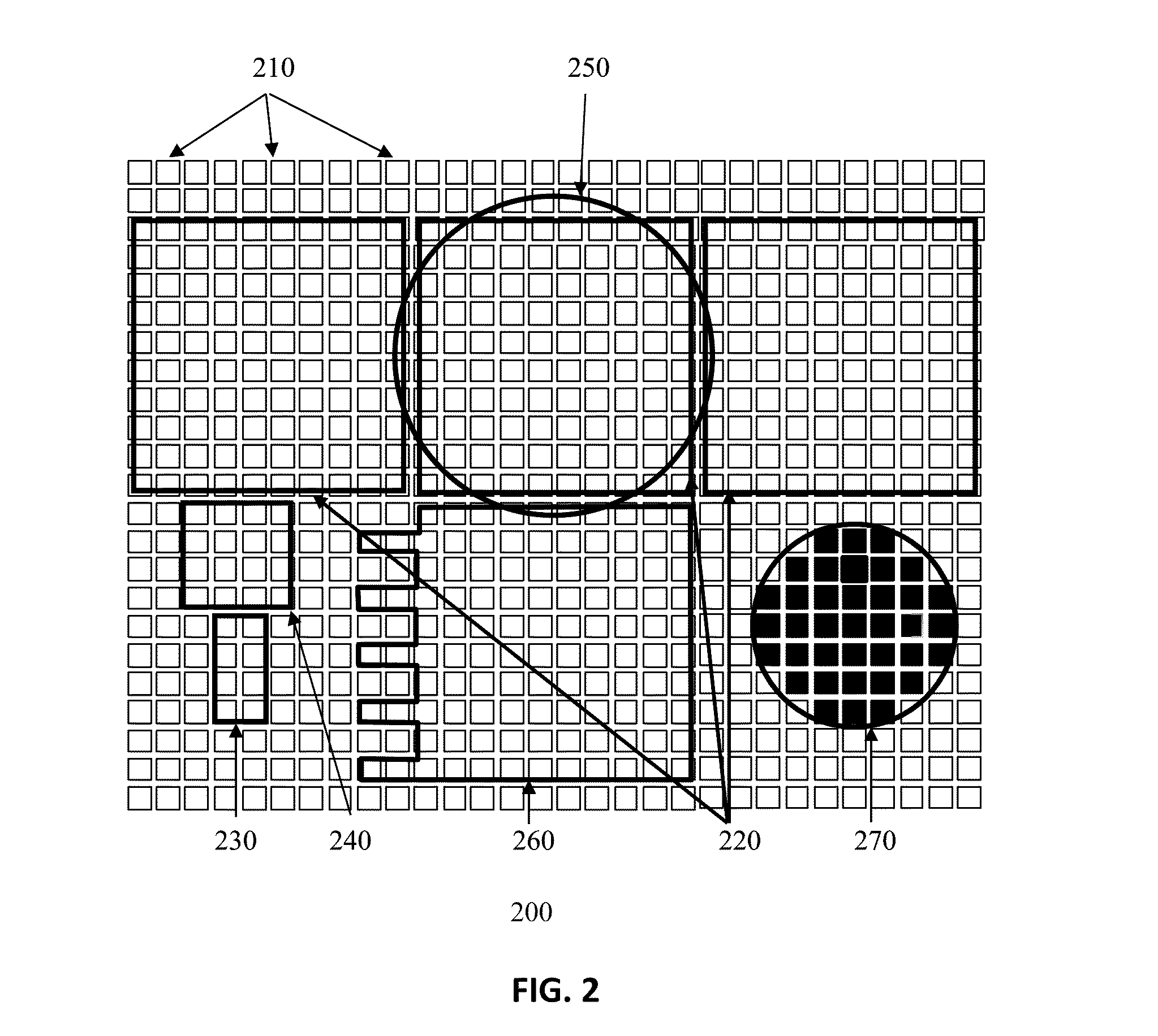
[0021]In yet another embodiment, besides the conventional control of the configured electrodes to perform typical microfluidic operations, special control sequences of the microelectrodes can offer advanced microfluidic operations in manipulations of droplets. Advanced microfluidic operations based on the EWOD Microelectrode Array Architecture may include: transporting droplets diagonally or in any directions; transporting droplets through the physical gaps by Interim bridging” technique; transporting

Problems solved by technology

Continuous-flow systems are adequate for many well-defined and simple biochemical applications, but they are unsuitable for more complex tasks requiring a high degree of flexibility or complicated fluid manipulations.
Unfortunately, the conventional LOC systems employing EWOD technique built to date are still highly specialized to particular applications.
Moreover, current applications and functions in the EWOD-LOC system are time-consuming and require costly hardware design, testing and maintenance procedures.
The most disadvantages about the conventional EWOD-LOC systems are the design of “hardwired” electrodes.
So therefore it may result in high non-recurring engineering costs, as well as the limited ability to update the functionality after shipping or partially re-configuring the LOC design.

Method used


Image

  • Droplet manipulations on EWOD microelectrode array architecture
  • Droplet manipulations on EWOD microelectrode array architecture
  • Droplet manipulations on EWOD microelectrode array architecture

Examples


Embodiment Construction

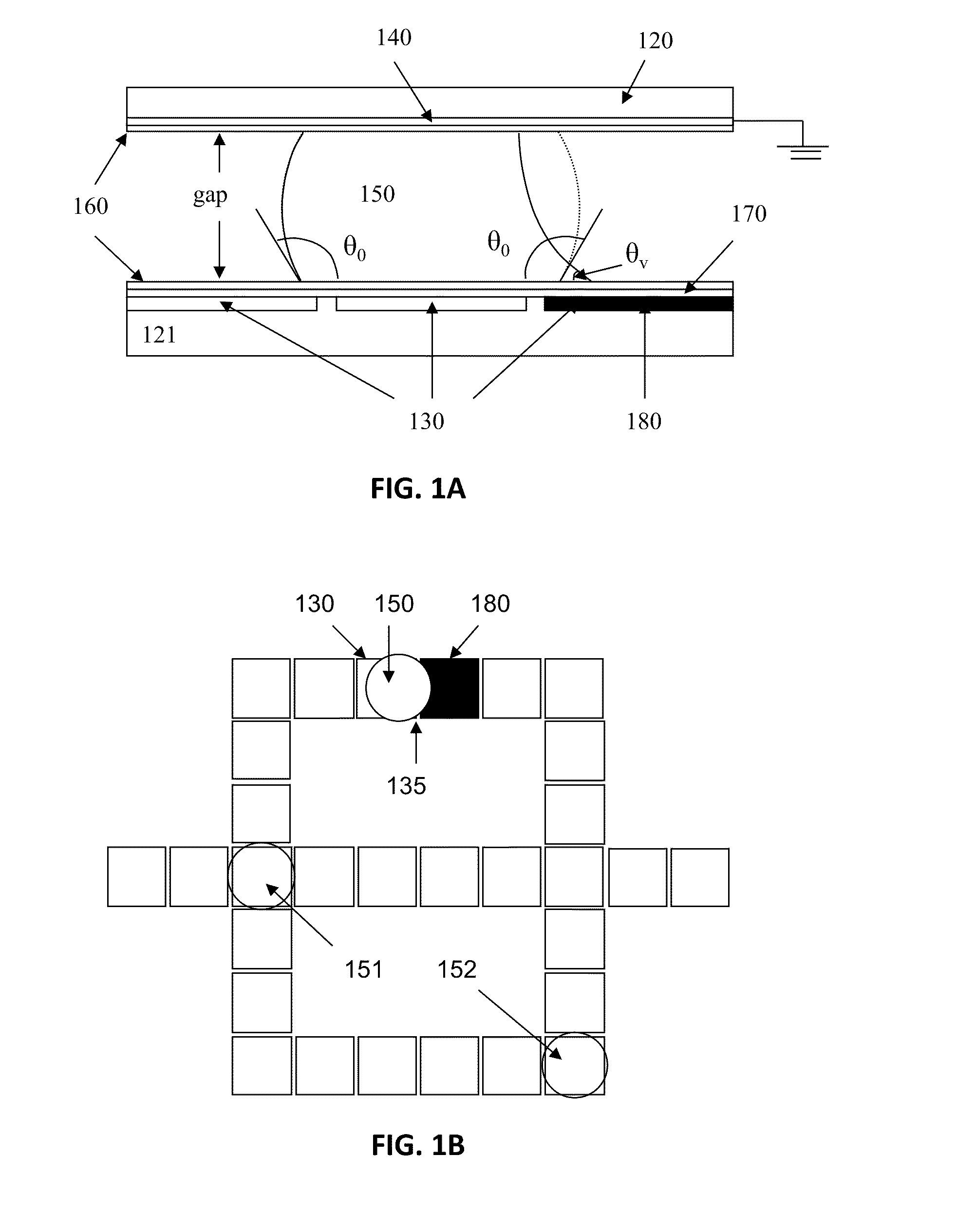
[0054]Referring to FIG. 1A, a conventional electrowetting microactuator mechanism (in small scale for illustration purposes only) is illustrated in FIG. 1A. EWOD-based digital microfluidic device 100 consists of two parallel glass plates 120 and 121, respectively. The bottom plate 121 contains a patterned array 130 of individually controllable electrodes, and the top plate 120 is coated with a continuous ground electrode 140. Electrodes are preferably formed by a material, such as indium tin oxide (ITO) that has the combined features of electrical conductivity and optical transparency in thin layer. A dielectric insulator 170, e.g., parylene C, coated with a hydrophobic film 160 such as Teflon AF, is added to the plates to decrease the wettability of the surface and to add capacitance between the droplet and the control electrode. The droplet 150 containing biochemical samples and the filler medium, such as the silicone oil or air, are sandwiched between the plates to facilitate the...


PUM

PropertyMeasurementUnit
Timeaaaaaaaaaa
Timeaaaaaaaaaa
Lengthaaaaaaaaaa

Abstract

A method of manipulating droplet in a programmable EWOD microelectrode array comprising multiple microelectrodes, comprising: constructing a bottom plate with multiple microelectrodes on a top surface of a substrate covered by a dielectric layer; the microelectrode coupled to at least one grounding elements of a grounding mechanism, a hydrophobic layer on the top of the dielectric layer and the grounding elements; manipulating the multiple microelectrodes to configure a group of configured-electrodes to generate microfluidic components and layouts with selected shapes and sizes, comprising: a first configured-electrode with multiple microelectrodes arranged in array, and at least one second adjacent configured-electrode adjacent to the first configured-electrode, the droplet disposed on the top of the first configured-electrode and overlapped with a portion of the second adjacent-configured-electrode; and manipulating one or more droplets among multiple configured-electrodes by sequentially activating and de-activating one or more selected configured-electrodes to actuate droplets to move along selected route.

Description

CROSS REFERENCE TO RELATED APPLICATIONS[0001]The present application claims benefit of priority under 35 U.S.C. 119(e) to: U.S. Patent Application 61 / 312,240, entitled “Field-Programmable Lab-on-a-Chip and Droplet Manipulations Based on EWOD Micro-Electrode Array Architecture” and filed Mar. 9, 2010; U.S. Patent Application 61 / 312,242, entitled “Droplet Manipulations on EWOD-Based Microelectrode Array Architecture” and filed Mar. 9, 2010; U.S. Patent Application 61 / 312,244, entitled “Micro-Electrode Array Architecture” and filed Mar. 10, 2010. The foregoing applications are hereby incorporated by reference into the present application in their entireties.[0002]The present application also incorporates by reference in its entirety co-pending U.S. Patent Application ______, entitled “Field Programmable Lab-on-a-Chip Based on Microelectrode Array Architecture”, and filed on the same date as the present application, namely, Feb. 17, 2011; co-pending U.S. Patent Application ______, entit...

Claims


Application Information

Patent Timeline
IPC IPC(8): C25B15/00
CPCB01L3/502792B01L2300/0816B01L2400/0427B01L2300/161B01L2300/089
Inventor WANG, GARY CHORNG-JYHHO, CHING YENHWANG, WEN JANGWANG, WILSON WEN-FU
Owner SPARKLE POWER
Learn More