
Fabric, a device with fabric and a manufacturing method for fabric

Inactive Publication Date: 2011-09-08
SEFAR
View PDF4 Cites 26 Cited by
  • Summary
  • Abstract
  • Description
  • Claims
  • Application Information

AI Technical Summary

Benefits of technology

[0016]The concept underlying the invention is the provision of the fabric manufactured from plastic threads preferably formed from solid material, in particular PET or PA threads, after the weaving process with an exclusively partial, i.e. not over the full surface area, electrically conducting coating. Expressed in another manner, by the coating of the fabric, preferably consisting exclusively of plastic, at least one electrical conductor (a flat conductor) is implemented. Thus a printed circuit, in particular a flexible printed circuit, is created on a fabric base, which can be used for a very wide variety of purposes. Expressed in yet another manner, at least one electrical conductor, preferably in the form of a resistance labyrinth or in the form of a conducting path network, is implemented by means of a metallic coating, and not by means of the threads themselves. In principle it is possible to insert into the fabric at least one conductor that is metallic on its outer surface, wherein a form of embodiment is preferred in which the fabric consists exclusively of threads which on their outer surfaces are formed from plastic, and still more preferably consist of solid plastic material. If the fabric designed in accordance with the concept of the invention is deployed as a screen printing fabric, the conductors manufactured by means of coating can then be used for the dissipation of static charge, in other words, for earthing the screen printing fabric to prevent the screen printing fabric from “sticking” to objects. In addition by means of this measure the attraction of dirt and dust particles is avoided. Here it is most particularly preferred if the screen printing fabric is earthed by means of partially metallic frames, in particular of aluminum, wherein direct contact between the screen printing fabric and an earthing cable is also conceivable.
[0019]With regard to the arrangement of the coating there are various possibilities. Thus for the function of the coating as a means of charge dissipation it is in principle sufficient to provide the coating on just one surface side of the screen printing fabric. Also it is conceivable to apply the coating on both sides in order to circumvent the risk of an incorrect installation. Most particularly preferred is the application of conducting paths on only one side so as to avoid short circuits between different conducting paths on different sides of the fabric.

Problems solved by technology

In practice the static charge leads to serious problems.
Thus it makes the handling of the screen printing fabric more difficult, since as a result of the static charge the screen printing fabric moves towards objects, and operators and remains “stuck” there.
Furthermore, there is the problem that statically charged screen printing fabrics attract dirt and dust particles from the environment, as a result of which the quality of the screens deteriorates, since during the application of a light-sensitive emulsion the dust and dirt are incorporated into it, leading to a deterioration of the resultant exposure and to clogged-up openings in the mesh.
In addition the resultant print can deteriorate severely if dust and dirt particles disrupt the optimal flow of color, or settle together with the color onto the item that is being printed.
Furthermore it has been observed that a static charge deteriorates the flow of color and the color release characteristics, in particular of metallic colors, or colors that can be attracted by charge.

Method used


Image

  • Fabric, a device with fabric and a manufacturing method for fabric
  • Fabric, a device with fabric and a manufacturing method for fabric
  • Fabric, a device with fabric and a manufacturing method for fabric

Examples


Embodiment Construction

[0051]In the figures the same elements, and elements with the same function, are identified the same reference symbols.

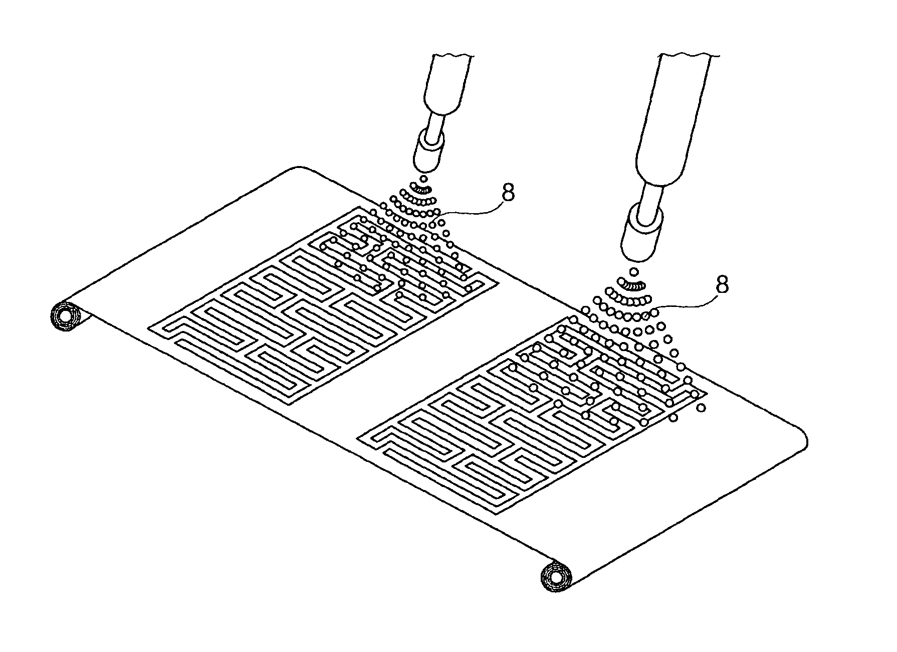
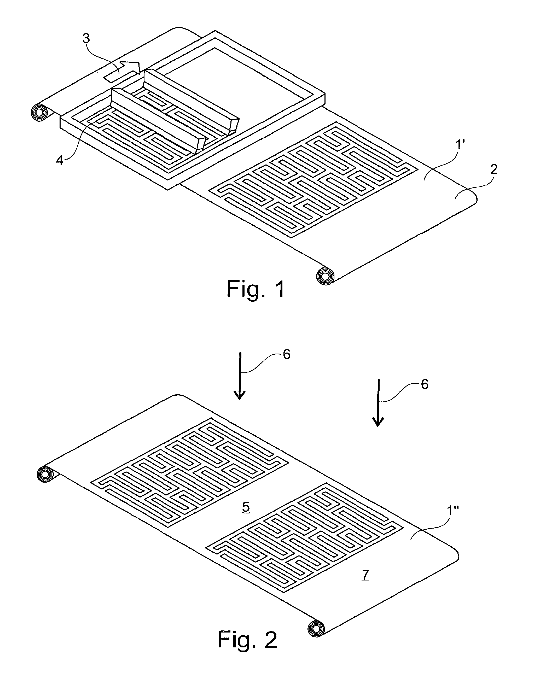
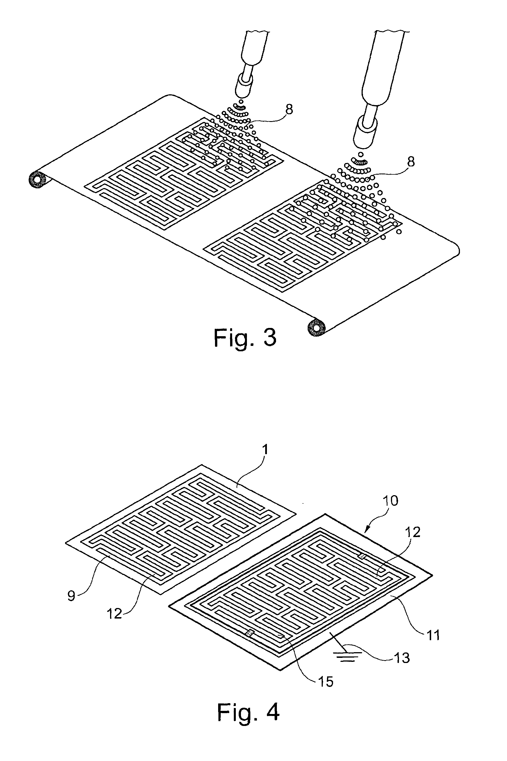
[0052]In FIG. 1 is shown a method step of a possible manufacturing method for the manufacture of a partially metallically coated fabric 1 shown in FIG. 4 above.

[0053]In the method an uncoated fabric 1′ is firstly provided as a fabric web. This uncoated fabric 1′ comprises, preferably consists of, threads 2 (weft threads and warp threads), which at least on their outer surface are formed from a polymer material (plastic).

[0054]FIG. 1 schematically represents the application (here by squeegee) of a mask 4, i.e. a masking material, in a printing direction 3 running transverse to the longitudinal extent of the fabric web, here by means of a screen printing method (alternatively, for example, by an ink jet printing method) in regions, which in the finished, partially coated fabric 1 (cf. FIG. 4) are not coated, or at least are not metallically coated.

[0055]In a method st...


PUM

PropertyMeasurementUnit
Thicknessaaaaaaaaaa
Thicknessaaaaaaaaaa
Thicknessaaaaaaaaaa

Abstract

A woven fabric (1) made from threads (2) that are formed from plastic at least one their outside surface. At least one surface side (7) of the fabric (1) is partially metallically coated.

Description

BACKGROUND OF THE INVENTION[0001]The invention concerns a fabric that is woven from threads that at least on their outer surface are formed from plastic. Furthermore the invention concerns a device with at least one fabric of this type, the use of such a fabric for different applications, and a method for the manufacture of a fabric.[0002]In practice for large-scale applications screen printing fabrics are today woven from plastic threads, mostly of PET or PA. The screen printing fabrics of known art become statically charged during handling, in particular during manufacture, or when they are being attached, in particular with an adhesive, onto screen printing frames, and also in the actual screen printing process. The static charge is particularly intense when the fabric is being unwound from a roller, during a process of attaching the screen printing fabric with adhesive and coating of the same, as well as when using a squeegee in the course of the printing process, as a result of...

Claims


Application Information

Patent Timeline
IPC IPC(8): B29C70/22B32B5/02
CPCB41F15/34B41N1/248D06M11/83D06M23/16H05K2203/107H05K9/009H05K1/038H05K3/027H05K2201/029D10B2401/16Y10T442/2008Y10T442/2418
Inventor CHABRECEK, PETERMEIER, HANSPETER
Owner SEFAR
Learn More