
Apparatus for improving efficiency and emissions of combustion

a technology of combustion process and apparatus, which is applied in the direction of combustion engine, charge feed system, non-fuel substance addition to fuel, etc., can solve the problems of increasing engine torque and horsepower output, increasing engine noise, and increasing engine torque and horsepower, so as to improve the efficiency and emissions of combustion process, increase the amount of ozone, and improve the effect of air flow disturban

Active Publication Date: 2011-09-08
CLACK TECH
View PDF3 Cites 4 Cited by
  • Summary
  • Abstract
  • Description
  • Claims
  • Application Information

AI Technical Summary

Benefits of technology

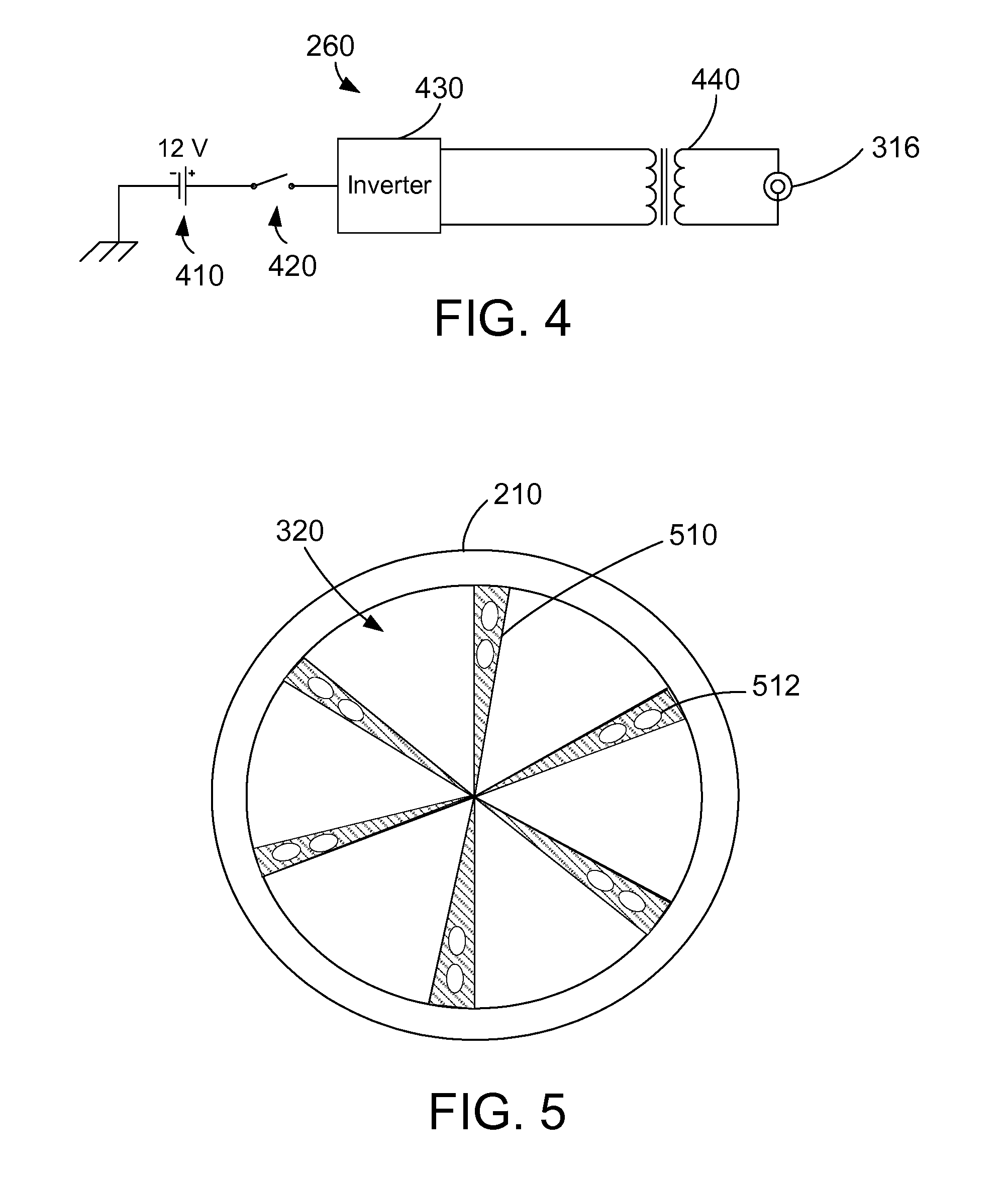
[0010]An apparatus is described to improve efficiency and emissions of a combustion process by producing sufficient amounts of ozone in the air flow to the combustion chamber to enable more complete and cleaner combustion of the fuel. A plurality of ozone elements for producing ozone are disposed within a housing that is placed in the air intake to a combustion chamber such as a diesel engine. The ozone elements are bonded together in a cross-shaped pattern inside the housing. The apparatus includes one or more vortex scrubbers or vanes in the housing to cause the air flow to have a vortex action to increase the amount of ozone that flows into the combustion chamber. The vortex scrubbers comprise multiple double fins that are attached inside the housing. The vortex scrubbers include holes and / or serrated edges to increase the disturbance of the air flow over the ozone elements to increase ozone production. The mass of the ozone elements have a preferred ratio of about 0.24 to about 0.26.

Problems solved by technology

The combination of a denser air charge and more oxygen increases the cylinder pressure, which increases the engine torque and horsepower output.
In particular, the prior art devices have not produced a sufficient volume of ozone (O3) to be effective.
Without a way to improve combustion, the industry will continue to suffer from inefficiency and poor engine performance.

Method used


Image

  • Apparatus for improving efficiency and emissions of combustion
  • Apparatus for improving efficiency and emissions of combustion
  • Apparatus for improving efficiency and emissions of combustion

Examples


Embodiment Construction

[0027]The description and claims herein are directed to an apparatus to improve the efficiency and emissions of a combustion process by producing sufficient amounts of ozone in the air flow to the combustion chamber to provide more complete and cleaner combustion of the fuel. In a preferred implementation, a plurality of ozone elements are disposed within a housing that is in placed in the air intake to a combustion chamber such as a diesel engine. The cell elements create an electrical plasma field that produces ozone.

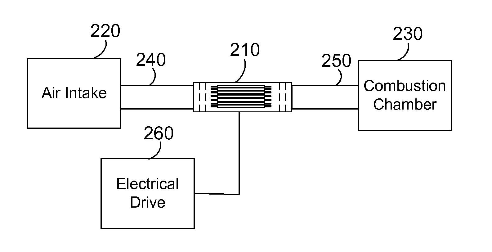
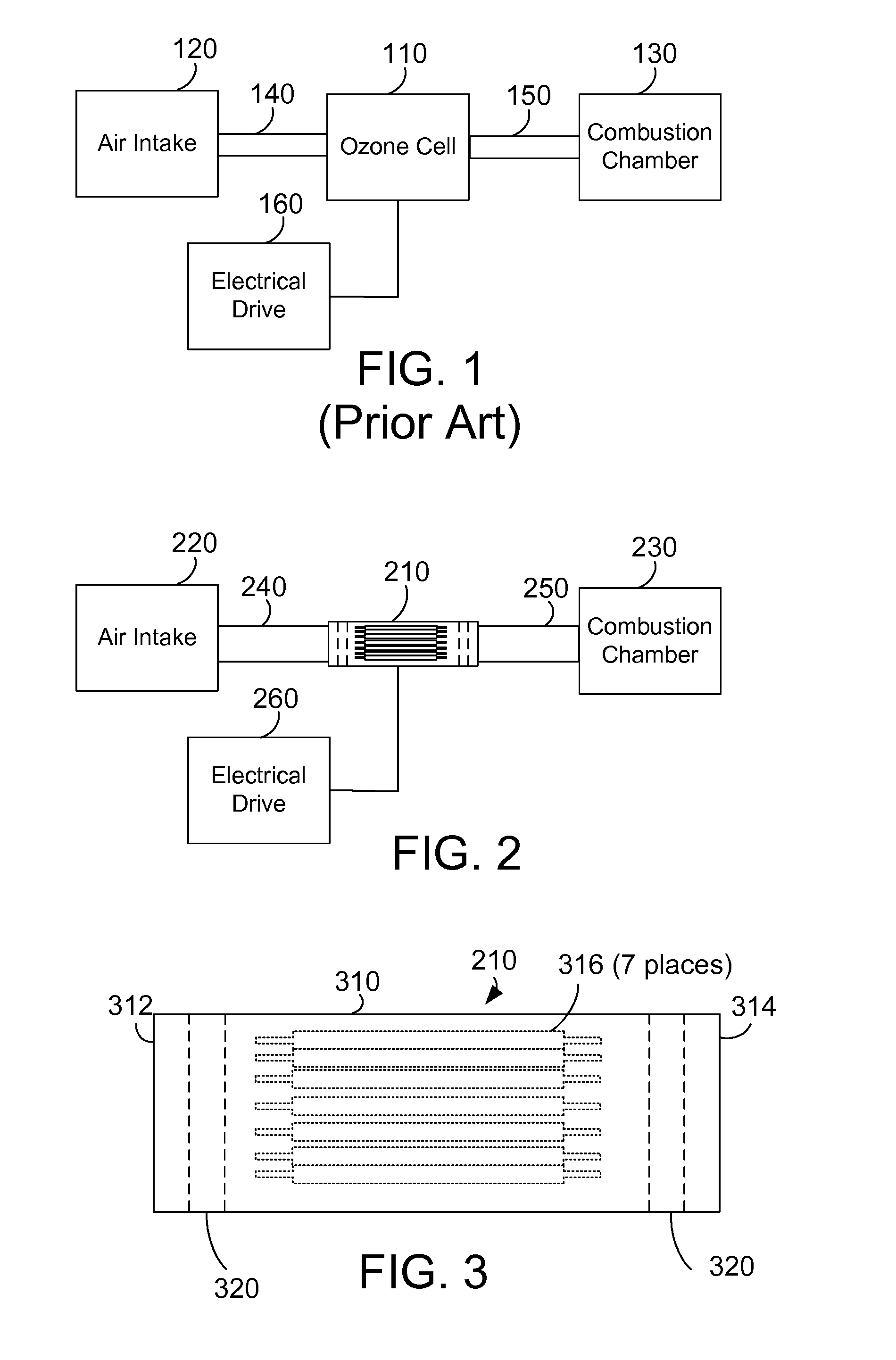
[0028]FIG. 2 shows an ozone cell 210 used to enhance the efficiency of combustion as described herein. The primary internal components are visible for illustration to match the description in FIG. 3. In FIG. 2, an ozone cell 210 is suitably disposed between an air intake 220 and a combustion chamber 230 to produce ozone and induce a charge in the air supply of a combustion process. Alternatively, the ozone cell is incorporated into the air intake pipe of an existing e...


PUM


Abstract

An apparatus improves the efficiency and emissions of a combustion process by producing sufficient amounts of ozone in the air flow to the combustion chamber to enable more complete and cleaner combustion of the fuel. A plurality of ozone elements for producing ozone are disposed within a housing that is placed in the air intake to a combustion chamber such as a diesel engine. The ozone elements are bonded together in a cross-shaped pattern inside the housing. The apparatus includes one or more vortex scrubbers or vanes in the housing to cause the air flow to have a vortex action to increase the amount of ozone that flows into the combustion chamber. The vortex scrubbers comprise multiple double fins that are attached inside the housing. The vortex scrubbers include holes and / or serrated edges to increase the disturbance of the air flow over the ozone elements to increase ozone production. The mass of the ozone elements have a preferred ratio.

Description

CROSS-REFERENCE TO PARENT APPLICATIONS[0001]This patent application is a divisional of U.S. Ser. No. 12 / 352,815 filed Jan. 13, 2009 which is a continuation-in-part of U.S. Ser. No. 11 / 972,801, filed Jan. 11, 2008 which is a continuation-in-part of U.S. Ser. No. 11 / 182,546 filed Jul. 15, 2005 by the same inventor and having the same title, and which are all incorporated herein by reference.BACKGROUND[0002]1. Technical Field[0003]The disclosure and claims herein generally relates to combustion processes, and more specifically relates to an apparatus for improving the efficiency and emissions of a combustion process such as an internal combustion engine.[0004]2. Background Art[0005]It has been observed that automobiles run better after a thunderstorm. It is believed that this phenomenon is primarily caused by the natural conditions that exist after an electrical storm, namely, the presence of ozone and an increase in the relative amount of negative ions in the air. These conditions inc...

Claims


Application Information

Patent Timeline
Patent Type & Authority Applications(United States)
IPC IPC(8): F02M27/00
CPCF02M25/12Y02T10/121F02M27/02Y02T10/12
Inventor CLACK, DAVID M.
Owner CLACK TECH
Learn More