Eureka AIR delivers breakthrough ideas for toughest innovation challenges, trusted by R&D personnel around the world.

Drive system and method for operating such a drive system, in particular for a motor vehicle

a drive system and drive technology, applied in the direction of toothed gearings, electric energy vehicles, belts/chains/gearings, etc., can solve the problems of increasing fuel consumption and emissions of pollutants, requiring a large amount of axial space, and not being able to activate the electric motor in the stationary state of the vehicle, etc., to achieve short shifting times, acceleration advantages, and wide application range of the drive system

Active Publication Date: 2011-09-01
DR ING H C F PORSCHE AG
View PDF12 Cites 15 Cited by
  • Summary
  • Abstract
  • Description
  • Claims
  • Application Information

AI Technical Summary

Benefits of technology

[0013]The invention has an advantage over the above-mentioned prior art approaches in that a structurally simple coupling of the electric motor to one of the component transmissions of the double clutch transmission is implemented. Furthermore, the drive system of the invention enables the electric motor to be activated when the vehicle is stationary, for example to start the internal combustion engine, without the drive axle of the motor vehicle being moved. Furthermore, the electric machine advantageously can be operated as a generator by the internal combustion engine to charge an energy store, for example during a waiting phase at a traffic light.
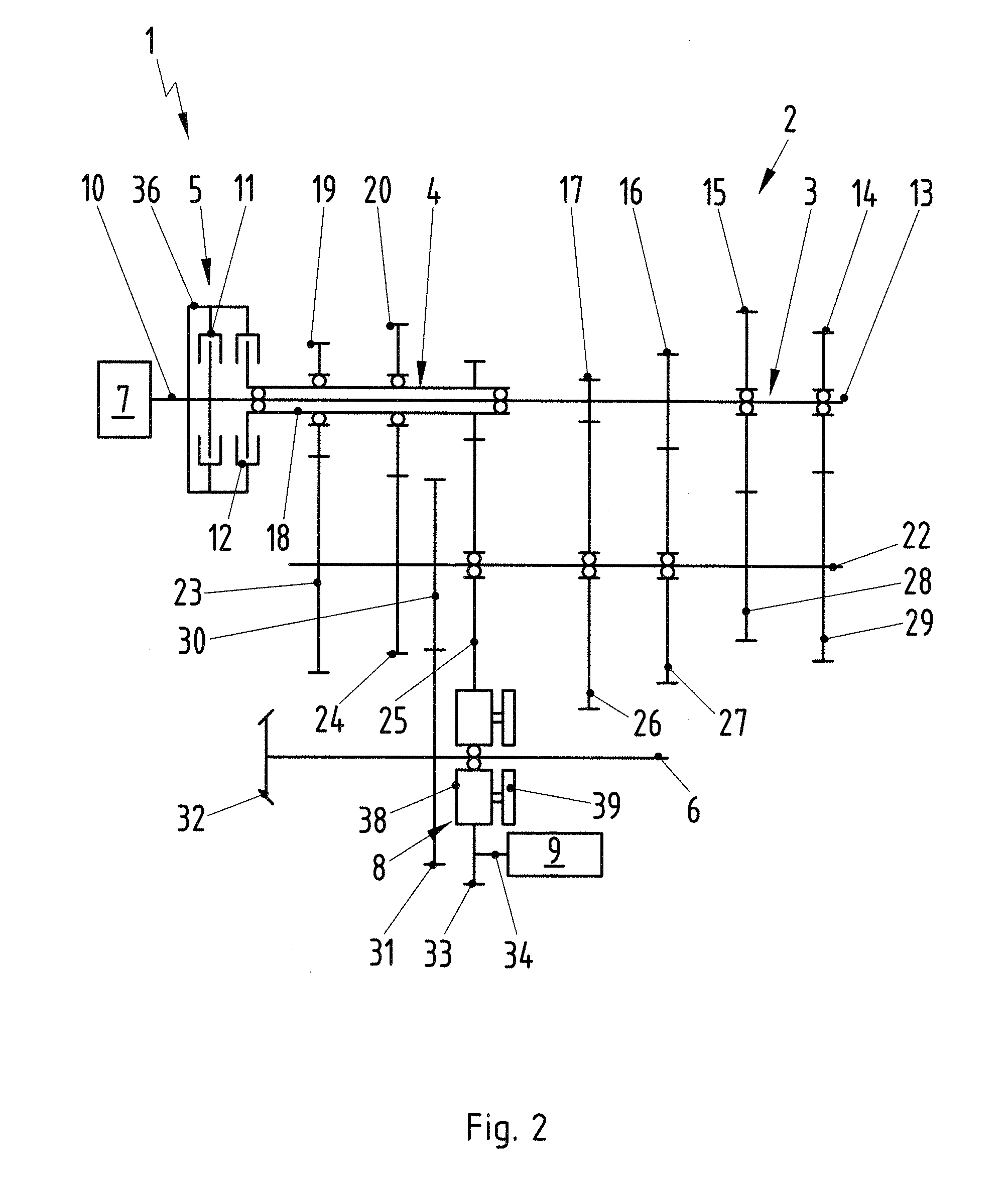
[0024]The electric machine may be connected operatively to the fixed gear via a spur gear and / or via a planetary gear mechanism. Thus, a desired transmission ratio between an electric machine and the component transmission can be attained in a comfortable fashion.

Problems solved by technology

Frequent starting and acceleration that occur, for example, in road traffic, preferably are carried out or assisted by the electric motor in a hybrid motor vehicle because the operation of the internal combustion engine with frequent load changes results in increased fuel consumption and emissions of pollutants.
These two designs require a large amount of axial space due to the arrangement of the electric motor.
It therefore is not possible to activate the electric motor in the stationary state of the vehicle, for example to start the internal combustion engine.

Method used


Image

  • Drive system and method for operating such a drive system, in particular for a motor vehicle
  • Drive system and method for operating such a drive system, in particular for a motor vehicle
  • Drive system and method for operating such a drive system, in particular for a motor vehicle

Examples


Embodiment Construction

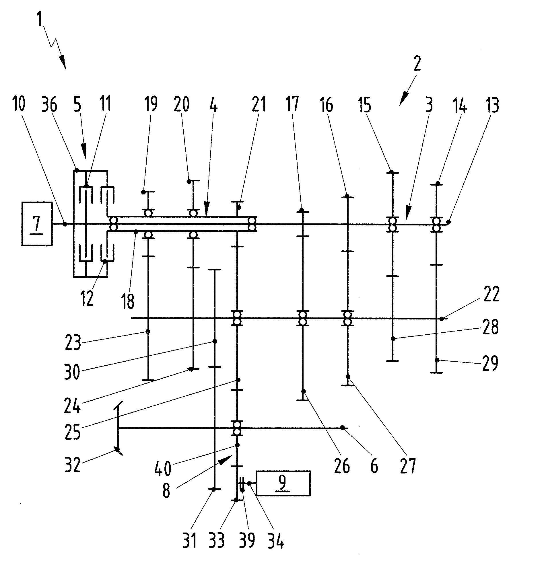
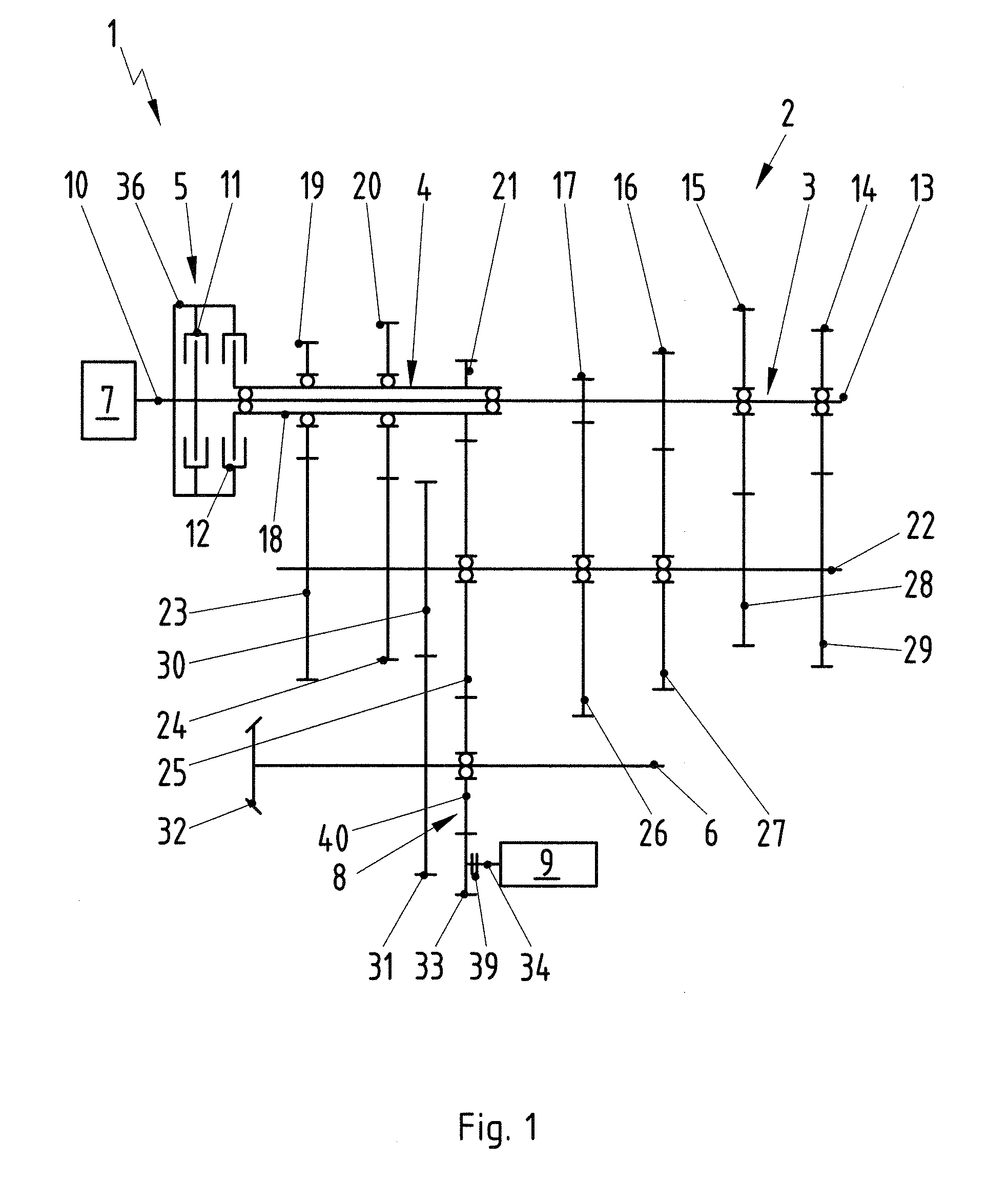
[0032]FIG. 1 is a schematic view of a drive system 1 having a double clutch transmission 2, an internal combustion engine 7 and an electric machine 9. The electric machine 9 can be operated either as an electric motor or as a generator. In the present embodiment, the double clutch transmission 2 has seven forward gear speeds and one reverse gear speed. However, it is also possible to use any other desired number of gear speeds. In the text which follows, a freely moving gear is understood to be a gearwheel that is mounted rotatably on a shaft, and a fixed gear is understood to be a gearwheel that is secured on the shaft in a frictionally locking or positively locking fashion. A freely moving gear may be connected, for example, via a shifting sleeve to a shaft in a frictionally locking fashion. In the case of rotating shafts, adaptation of the rotational speed of the freely moving gear to the shaft is carried out by synchronization. The internal combustion engine 7 is connected in a ...


PUM


Abstract

A drive system (1) for a motor vehicle has a double clutch transmission (2), with two component transmissions (3, 4), a double clutch (5) and an output shaft (6). An internal combustion engine (7) optionally can be connected operatively to one of the component transmissions (3, 4) via the double clutch (5) to drive the output shaft (6). A gear drive (8) is arranged rotatably on the output shaft (6). An electric machine (9) can be connected operatively via the gear drive (8) to at least one fixed gear (16, 17, 21) of one of the component transmissions (3, 4) to drive the output shaft (6) and / or to recover kinetic energy from the drive system (1).

Description

CROSS-REFERENCE TO RELATED APPLICATION[0001]This application claims priority under 35 USC 119 to German Patent Application No. 10 2010 010 435.3, filed on Feb. 26, 2010, the entire disclosure of which is incorporated herein by reference.BACKGROUND OF THE INVENTION[0002]1. Field of the Invention[0003]The invention relates to a drive system and to a method for operating such a drive system, in particular for a motor vehicle.[0004]2. Description of the Related Art[0005]The invention can be applied to any vehicle, but the invention and the problems on which the invention is based will be explained in more detail with respect to a passenger car.[0006]A hybrid vehicle generally is considered a vehicle with a drive system that uses a plurality of drive units, such as an internal combustion engine and an electric motor. Parallel hybrid drives usually should be used to generate the highest possible energetic efficiency. A parallel hybrid drive permits the electric motor and the internal comb...

Claims


Application Information

Patent Timeline
Patent Type & Authority Applications(United States)
IPC IPC(8): B60K6/365B60K6/42
CPCY10T74/19228Y02T10/6221B60K6/547F16H3/006B60K6/48Y10T74/19223Y02T10/62B60K2006/4825B60K2006/4816B60K2006/4833
Inventor SCHRAGE, HENRIK
Owner DR ING H C F PORSCHE AG
Why Eureka
Eureka Blog
Learn More