
Propeller unit for marine vessel propulsion device and marine vessel propulsion device including the same

a technology for marine vessels and propellers, applied in marine propulsion, rotary propellers, vessel construction, etc., can solve the problems of large inertial mass of propeller units, insufficient dampers to just be able, and insufficient dampers to prevent impact noise during travel through rocky reef regions.

Active Publication Date: 2011-09-01
YAMAHA MOTOR CO LTD
View PDF9 Cites 21 Cited by
  • Summary
  • Abstract
  • Description
  • Claims
  • Application Information

AI Technical Summary

Benefits of technology

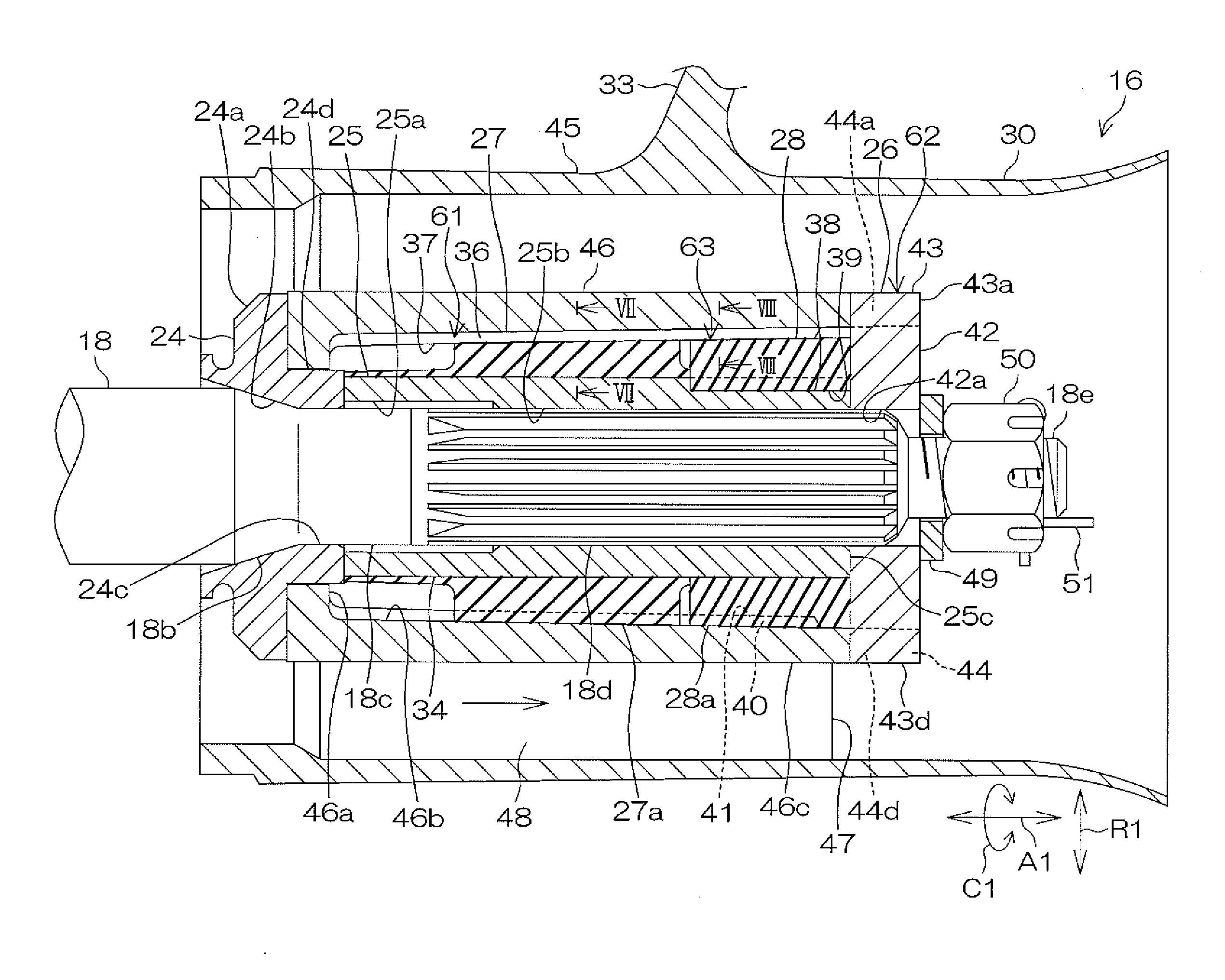
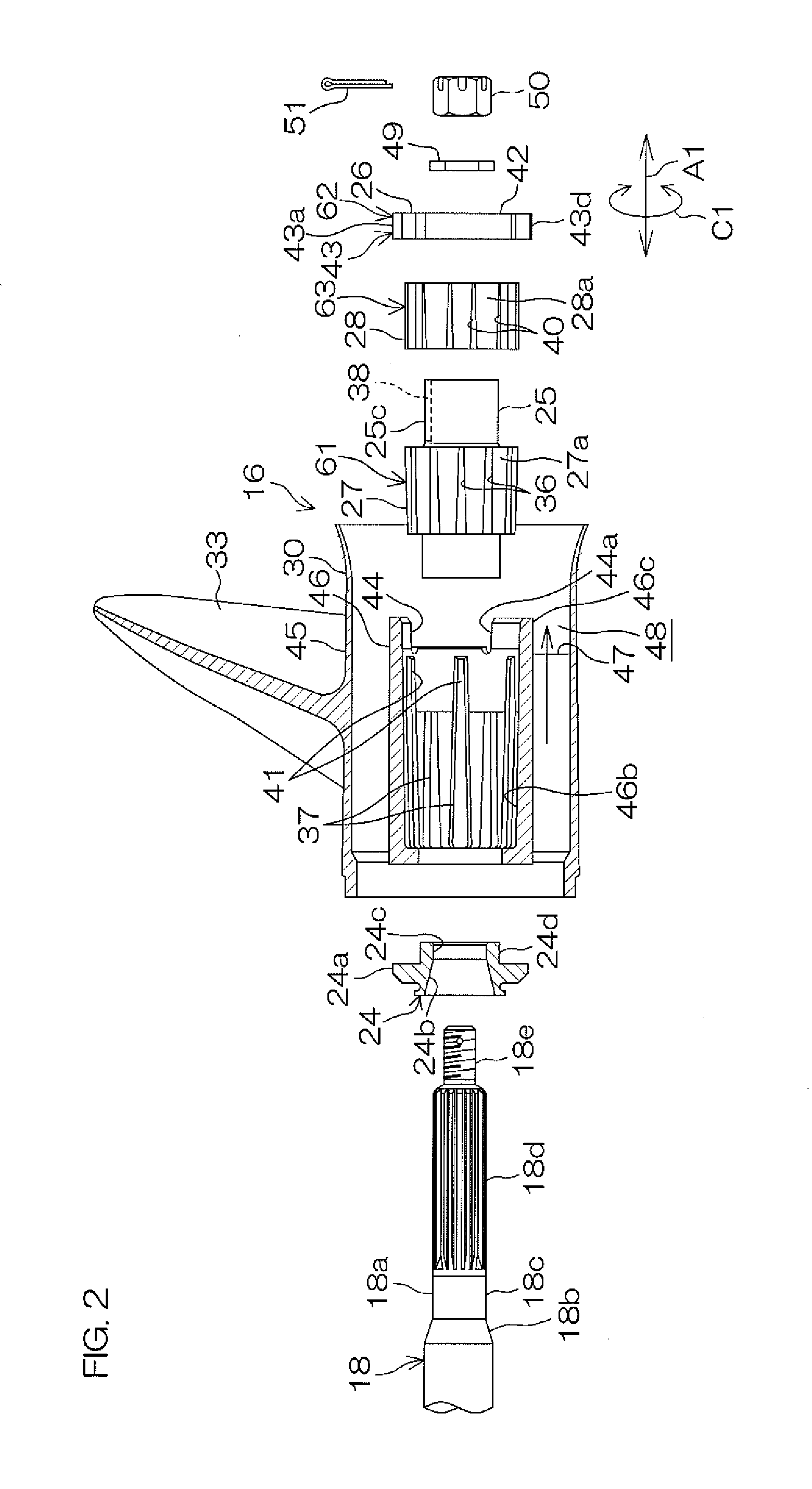
[0015]According to this arrangement, the first driving force transmitting member is an elastic member and can thus absorb shift shock and other impacts applied to the propeller shaft. The second driving force transmitting member is provided apart from the first driving force transmitting member. The driving force applied to the propeller shaft can thus be transmitted to the outer cylinder (blades) via the second driving force transmitting member when the driving force transmitted to the propeller shaft is not less than the reference driving force. The driving force that the first driving force transmitting member must transmit from the propeller shaft to the outer cylinder may thus be small and a material of the first driving force transmitting member can thus be made soft. An effect of reducing shift shock and other impacts by the first driving force transmitting member can thereby be increased. When the driving force transmitted to the propeller shaft is less than the reference driving force, the second driving force transmitting member is not coupled to the outer cylinder in a driving force transmittable manner. In this case, the driving force applied to the propeller shaft is transmitted to the outer cylinder via the first driving force transmitting member. The impact absorbing effect by the first driving force transmitting member can thus be exhibited reliably.
[0054]According to this arrangement, a marine vessel propulsion device can be provided with which shift shock and other impacts acting on the propeller shaft can be prevented, the driving force from the propeller shaft can be transmitted to the blades, and impact noise during travel through a rocky reef region can be prevented and minimized.

Problems solved by technology

A main cause of the shift shock is a large inertial mass of the propeller unit.
During shift-out, although a shift shock occurs because the large inertial mass is cut off from the engine, the shift shock is not as strong as that during shift-in.
However, it is insufficient for the damper to just be able to alleviate the shift shock and it must also be able to transmit the driving force of the propeller shaft to the blades.
It was thus difficult to improve both functions at the same time.

Method used


Image

  • Propeller unit for marine vessel propulsion device and marine vessel propulsion device including the same
  • Propeller unit for marine vessel propulsion device and marine vessel propulsion device including the same
  • Propeller unit for marine vessel propulsion device and marine vessel propulsion device including the same

Examples


Embodiment Construction

[0073]Preferred embodiments of the present invention shall now be described in detail with reference to the attached drawings.

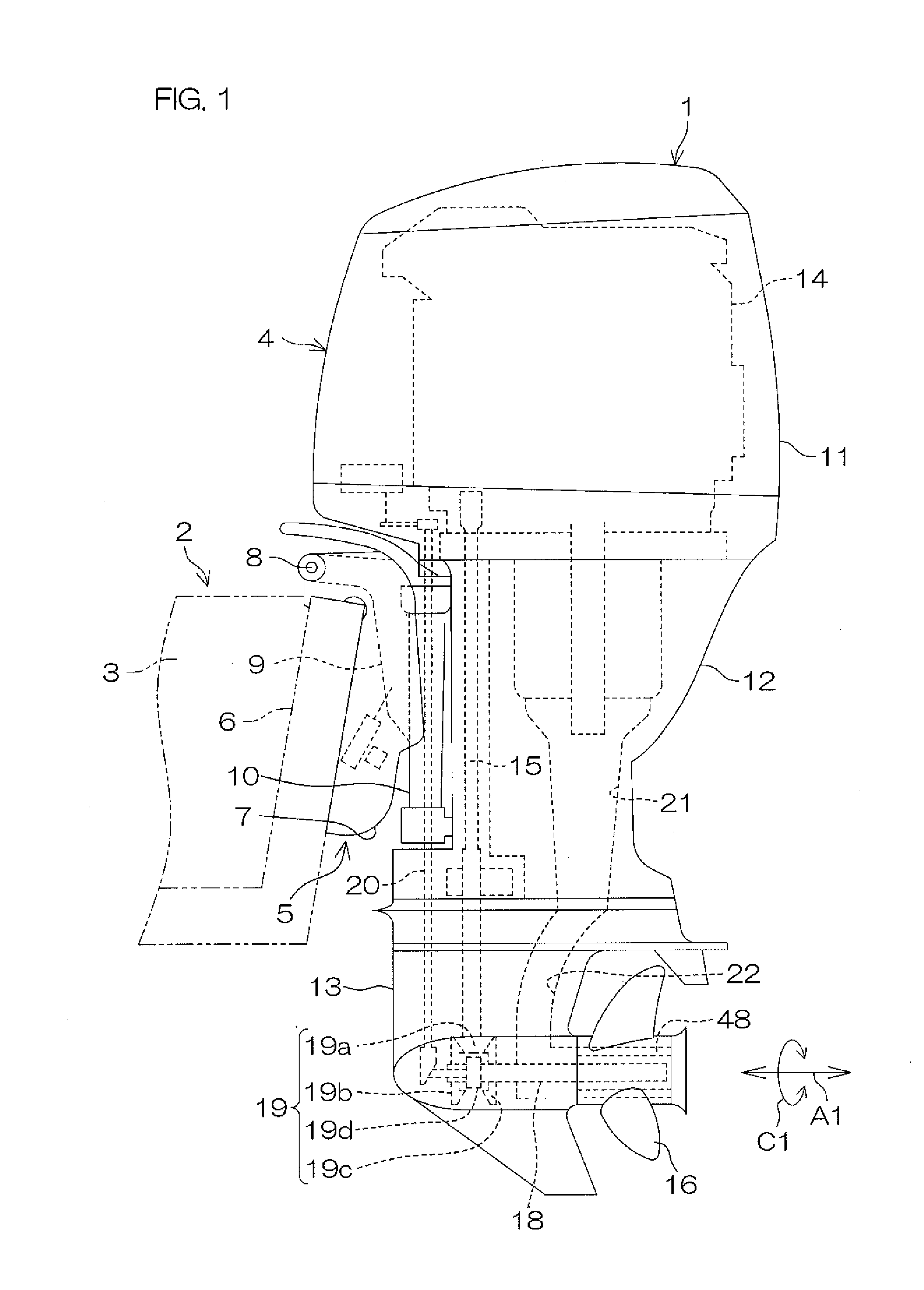
[0074]FIG. 1 is a schematic side view of a general arrangement of an outboard motor according to a preferred embodiment of the present invention.

[0075]The outboard motor 1 is an example of a “marine vessel propulsion device” according to the present preferred embodiment of the present invention. The outboard motor 1 is used upon attachment to a stern (transom) of a hull 3 of a marine vessel 2 and generates a propulsive force that drive the marine vessel 2 forward or in reverse. The outboard motor 1 includes an outboard motor main body 4, and an attachment mechanism 5 arranged to attach the outboard motor main body 4 to the hull 3.

[0076]The attachment mechanism 5 includes a clamp bracket 7 detachably fixed to a stern plate 6 of the hull 3, and a swivel bracket 9 coupled to the clamp bracket 7 in a manner enabling pivoting about a tilt shaft 8 as a horizontal p...


PUM


Abstract

A propeller unit for a marine vessel propulsion device includes an inner cylinder arranged to be fixed to the propeller shaft, an outer cylinder, a first driving force transmitting member, and a second driving force transmitting member. The propeller unit for marine vessel propulsion device further includes a pair of first engaging portions, and a pair of second engaging portions provided on the outer cylinder and the second driving force transmitting member. The pair of second engaging portions are arranged such that the mutual engaging of the respective second engaging portions is disengaged when a driving force is not transmitted to the propeller shaft and are arranged such that the respective second engaging portions become mutually engaged in a driving force transmittable manner by elastic deformation of the first driving force transmitting member when a driving force that is not less than a reference driving force is transmitted to the propeller shaft.

Description

BACKGROUND OF THE INVENTION[0001]1. Field of the Invention[0002]The present invention relates to a propeller unit for a marine vessel propulsion device arranged to be attached to a propeller shaft driven by an engine or other motor and relates to a marine vessel propulsion device that includes the propeller unit.[0003]2. Description of Related Art[0004]A propeller unit of a marine vessel propulsion device includes, for example, an inner cylinder fixed to a propeller shaft, an outer cylinder surrounding the inner cylinder, and a cylindrical damper made of rubber and disposed between the inner cylinder and the outer cylinder. The damper is fixed to the inner cylinder, and the damper that is made integral with the inner cylinder is press fitted into the outer cylinder. A driving force transmitted from the engine to the propeller shaft is transmitted via the inner cylinder and the damper to the outer cylinder and rotates blades fixed to the outer cylinder. The blades thereby push the wa...

Claims


Application Information

Patent Timeline
IPC IPC(8): B63H1/14B63H23/08
CPCB63H23/34B63H20/14B63H1/15B63H2023/342
Inventor TSUNEKAWA, HIROYUKIYUKAWA, SHUNSUKE
Owner YAMAHA MOTOR CO LTD
Learn More