Protection System of a Doubly-fed Induction Machine

a protection system and induction machine technology, applied in the direction of machines/engines, electric generator control, dynamo-electric converter control, etc., can solve the problem of quite low cost of short response time, achieve the effect of protecting the crowbar from overheating, minimizing the effort to protect the crowbar, and preventing overheating

Active Publication Date: 2011-09-01
CONVERTERTEC DEUT GMBH
View PDF6 Cites 18 Cited by
  • Summary
  • Abstract
  • Description
  • Claims
  • Application Information

AI Technical Summary

Benefits of technology

[0020]In order to protect the crowbar from overheating, the converter controller controls the switch-unit to switch off the doubly-fed induction machine from the grid.
[0021]In order to minimize efforts to protect the crowbar by the converter controller according to a preferred embodiment of the inventive method, the converter controller estimates a rotor current by using a machine model of a doubly-fed induction machine and measured values for example of the stator voltage, the stator current and the angle between stator and rotor voltage, whereas the crowbar current is determined from the difference of the estimated rotor current and the measured machine side converter current. With this measure, the converter controller is enabled to detect the crowbar current and to protect the crowbar from overheating without the necessity of expensive A/D-converters.
[0022]According to a next embodiment of the inventive method, a doubly-fed induction machine is switched-off from the grid by the converter controller if a critical load of the crowbar is determined by c...

Problems solved by technology

The expenses to achieve short response time are quite low, because only...

Method used


Image

  • Protection System of a Doubly-fed Induction Machine
  • Protection System of a Doubly-fed Induction Machine
  • Protection System of a Doubly-fed Induction Machine

Examples


Embodiment Construction

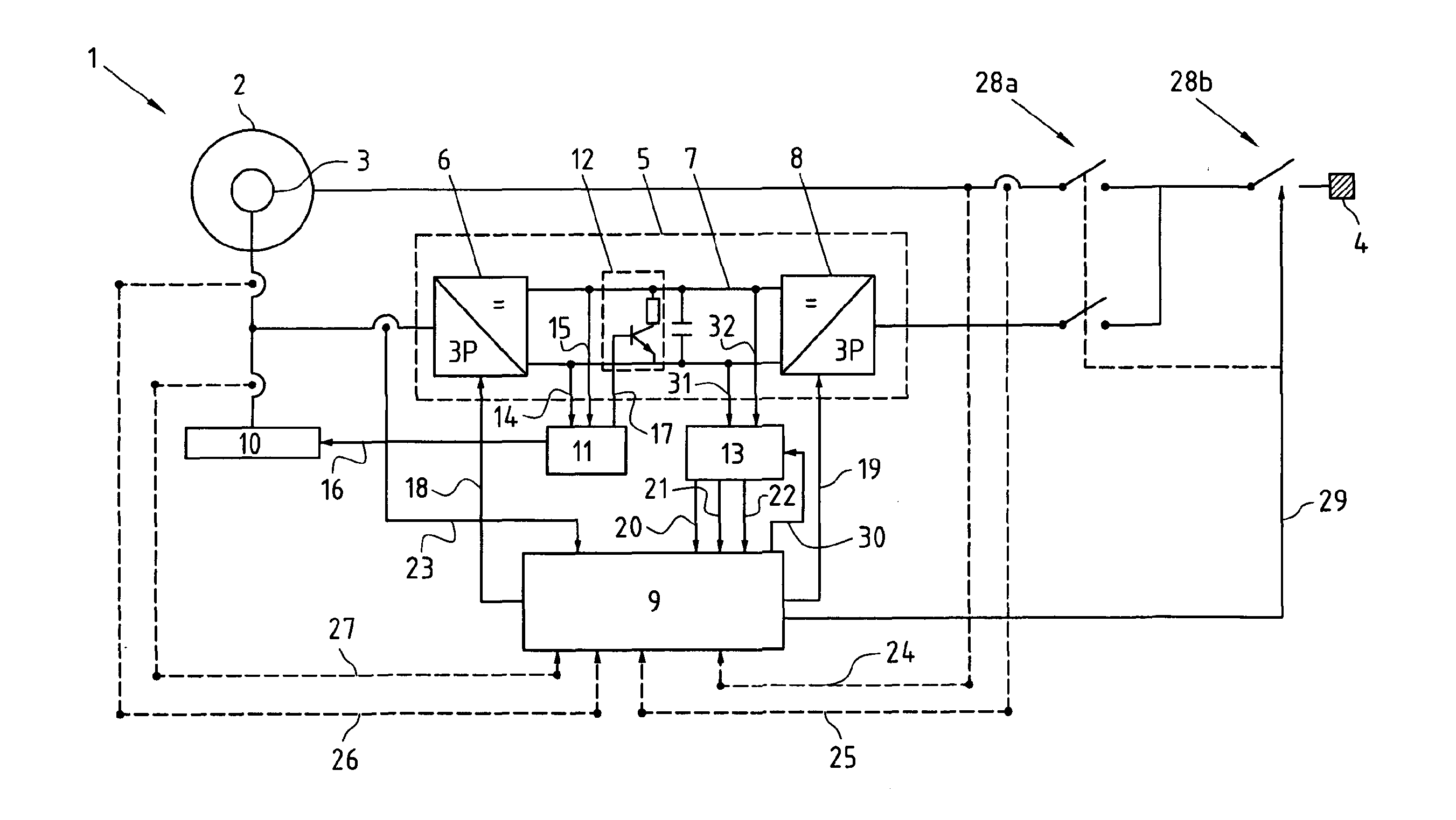
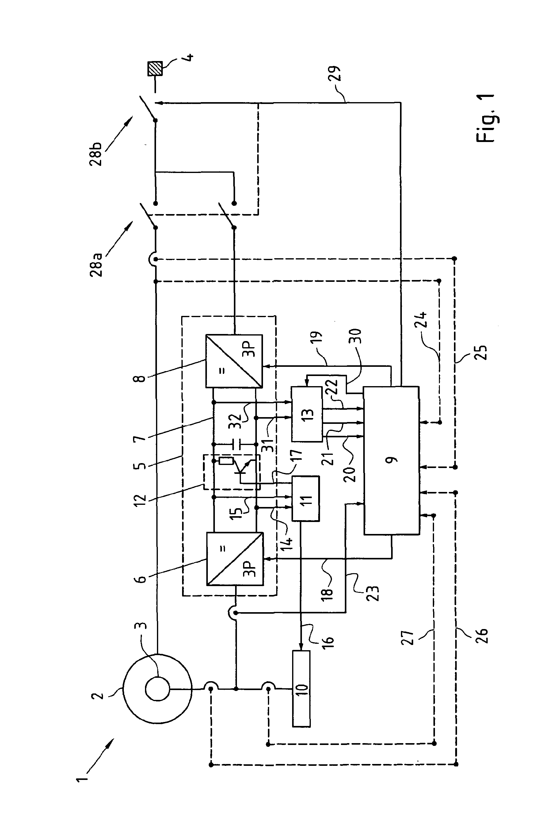
[0028]FIG. 1 shows a doubly-fed induction machine 1 with a stator 2 and a rotor 3. In the present embodiment the stator 2 is directly connected to the grid 4. However, a transformer is not shown to simplify matters. The rotor 3 of the doubly-fed induction machine 1 is connected via a converter 5 to the grid 4, whereas the converter 5 consists of a machine side converter 6, a DC-link 7 and a line side converter 8. Furthermore, a converter controller 9 is provided to control machine side converter 6 and the line side converter 8 in order to the function of the doubly-fed induction machine to provide electrical power to the grid.

[0029]The inventive protection system shown in FIG. 1 comprises additionally a crowbar 10 and a separate protection device 11. Said protection device 11 is connected to the crowbar 10 as well as to a DC-chopper 12 provided in the DC-link 7. Moreover, a measurement device 13 is provided, which measures the DC-link voltage by means 31, 32 in order to provide valu...


PUM


Abstract

The invention relates to a protection system of a doubly-fed induction machine, the system comprises a doubly-fed induction machine with a stator and a rotor, the stator of said doubly-fed induction machine is connected to a grid and the rotor of said doubly-fed induction machine is connected to the grid via a converter, said converter comprises a machine side converter, a DC-link and a line side converter. The system comprises additionally at least one crowbar, said crowbar is connected to the rotor, at least one DC-chopper provided in the DC-link, a converter controller and a separate protection device. The object of the present invention to provide a protection system and a protection method of a doubly-fed induction machine which can be easily used with high sampling rates and which provides a good protection for the doubly fed induction machine is resolved in that the DC-chopper and the crowbar are controlled with the separate protection device.

Description

CROSS-REFERENCE TO RELATED PATENT APPLICATIONS[0001]This patent application is a continuation of pending PCT / EP2008 / 064140, filed Oct. 20, 2008, the entire teachings and disclosure of which are incorporated herein by reference thereto.FIELD OF THE INVENTION[0002]The invention relates to a protection system of a doubly-fed induction machine.BACKGROUND OF THE INVENTION[0003]Doubly-fed induction machines are used in connection with wind power stations located alone or in wind parks. In principle the doubly-fed induction machine is also used in water power stations. Due to the demand to use wind parks with a weak connection to the grid, for example in the case of an off-shore wind park, unbalanced grid operation of the wind power station in the case of a grid fault has to be taken into consideration in construction of control units of the doubly-fed induction machines. One aim is to avoid disconnection of the wind power stations from the grid for example in the case of drop of the grid ...

Claims


Application Information

Patent Timeline
IPC IPC(8): H02H7/06H02P9/04
CPCF03D9/003H02P9/006H02P9/007H02P2101/15H02P29/024H02P2207/073Y02E10/72H02P9/10F03D9/255H02P29/0241
Inventor ENGELHARDT, STEPHANKOCK, LARS
Owner CONVERTERTEC DEUT GMBH
Why Eureka
Try Eureka