
Communication apparatus, relay apparatus, communication system and communication method

a communication apparatus and relay technology, applied in the field of communication systems, can solve the problems of inability to determine the transmission timing of all apparatuses other than the predetermined apparatus, the processing load of each apparatus is large, and the respective decision transmission timing cannot be efficiently converged, so as to reduce the processing load of each communication apparatus, prevent the message hold from becoming longer and larger, and improve communication efficiency

Inactive Publication Date: 2011-08-25
AUTONETWORKS TECH LTD +2
View PDF17 Cites 33 Cited by
  • Summary
  • Abstract
  • Description
  • Claims
  • Application Information

AI Technical Summary

Benefits of technology

[0022]The present invention is made in view of such circumstances, and has an object to provide a communication apparatus, communication system and communication method, where plural apparatuses are connected to a communication line with a bus topology, each apparatus performs transmission timing adjustment, a communication apparatus connected to the communication line perform the transmission timing adjustment effectively at the time when a collision occurs on the communication line, the communication collision is reduced efficiently as well as the processing load amount is reduced for each apparatus, and each apparatus performs the transmission timing adjustment effectively, in order to improve the communication efficiency.
[0059]Especially, the on-vehicle LAN performing a wire communicating through communication lines connected with a bus topology is desired to perform the efficient high speed communication, with reducing the communication collision, but without utilizing a resolution method making the communication speed become faster and giving a large amount of processing load on each apparatus. Even in such an especial case, the present invention can effectively reduce the communication collision on the communication line and can improve the communication efficiency.

Problems solved by technology

However, in the case of utilizing a configuration that determines the transmission timing based on a data transmission from a predetermined apparatus, there is a risk that the transmission timings for all apparatuses other than the predetermined apparatus cannot be determined when a failure happens to the predetermined apparatus and the predetermined apparatus cannot transmit data.
In addition, in the case of utilizing a configuration that independently makes each apparatus decide the transmission timing based on a data transmission from another apparatus, respective decided transmission timing may not converge efficiently.
Further, in the case of utilizing a configuration that independently makes each apparatus count the data transmission from another apparatus all the time to determine the transmission timing, each apparatus must take a larger amount of processing load.

Method used


Image

  • Communication apparatus, relay apparatus, communication system and communication method
  • Communication apparatus, relay apparatus, communication system and communication method
  • Communication apparatus, relay apparatus, communication system and communication method

Examples


embodiment 1

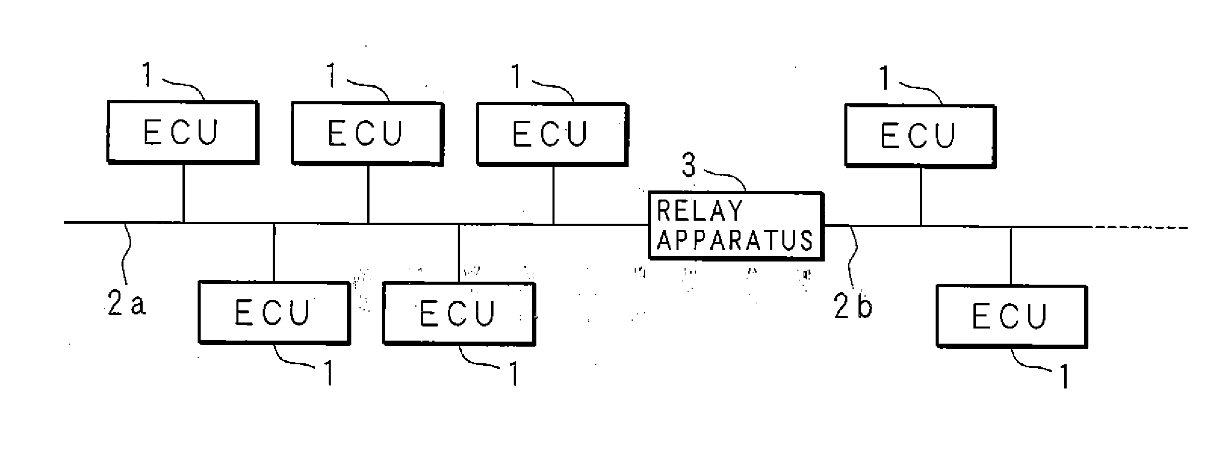
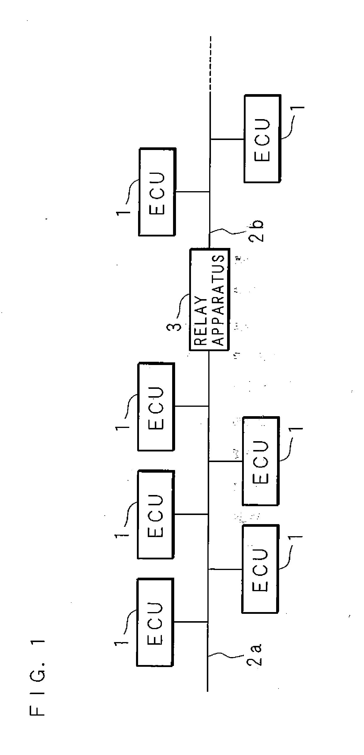
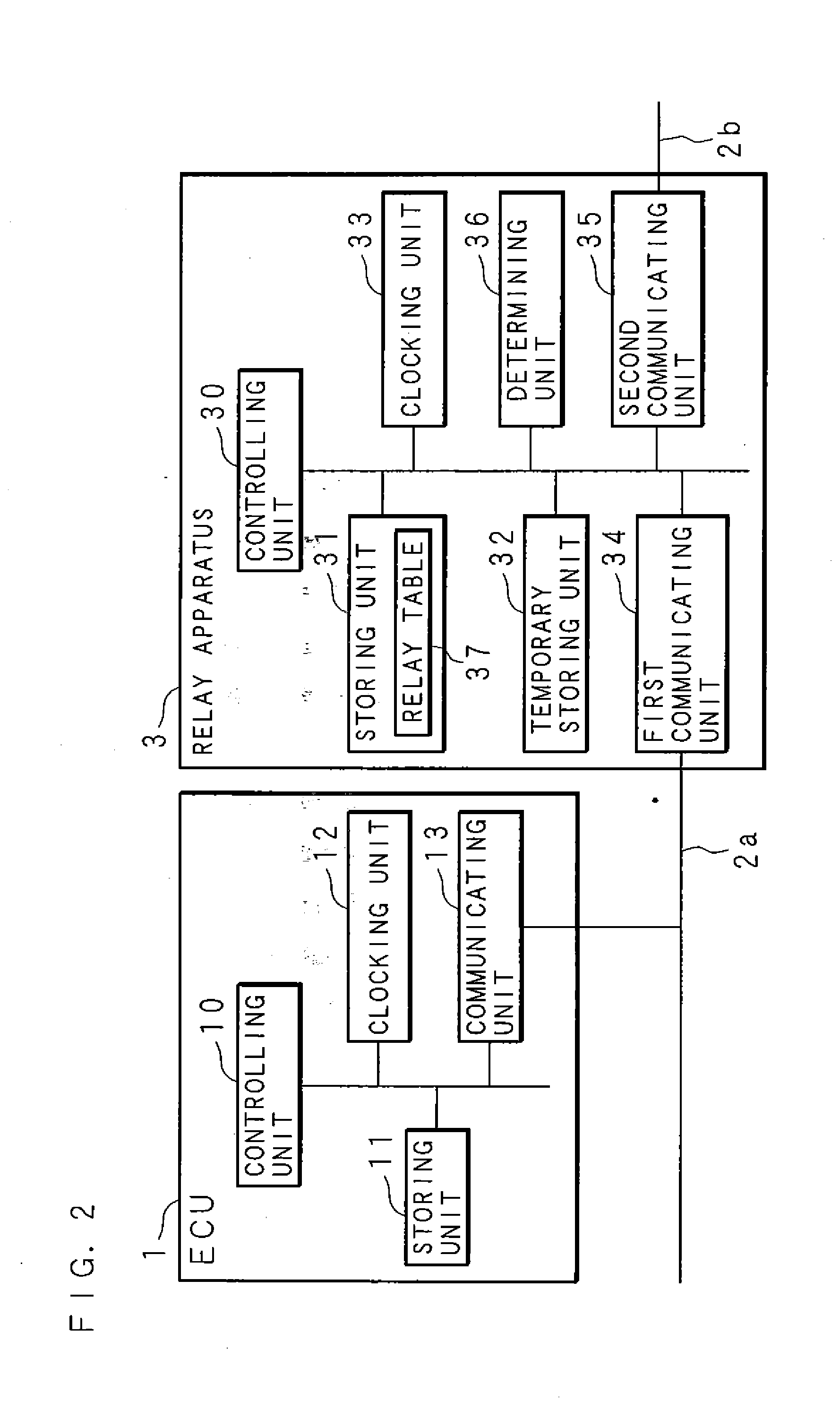
[0086]FIG. 1 is a configuration view showing a configuration of the on-vehicle communication system according to an embodiment 1. The on-vehicle communication system includes: ECUs 1, 1, . . . that are apparatuses transmitting messages; communication lines 2a, 2b, each of which is connected to a group of ECUs 1, 1, . . . ; and a relay apparatus 3 that is connected to communication lines 2a, 2b and relays data transmitted between ECUs 1, 1, . . . .

[0087]ECUs 1, 1, . . . are respectively connected to communication lines 2a, 2b with a bus topology. For implementing functions of car, the ECUs 1, 1, . . . can transmit data including numerical information representing several physical values, such as a counted value, calculated value and control value, or can control an engine, brake and the like, with a microcomputer. When transmitting data including the numerical information, the ECUs 1, 1, . . . performs transmission based on the controller area network (CAN) protocol of a “message” in...

embodiment 2

[0147]In the embodiment 1, the bias of transmission timing is considered in accordance with the determination whether the number of base time intervals during which no message is transmitted is more than the predetermined number among the plural base time intervals included in the monitoring period, and then the requirement of transmission timing adjustment for ECUs 1, 1, . . . is determined in accordance with the consideration. In the case of an embodiment 2, however, it is considered that the bias occurs in the timings of messages transmitted from ECUs 1, 1, . . . when the number of messages transmitted during a base time interval is over the limitation, and then it is, determined in accordance with the consideration that transmission timing adjustment should be performed.

[0148]The hardware configuration of the on-vehicle communication system according to the embodiment 2 is similar to the hardware configuration according to the embodiment 1, thus the same numerals are provided to...

embodiment 3

[0157]In the embodiment 1, the bias of transmission timing is considered in accordance with the determination whether the number of base time intervals during which no message is transmitted is more than the predetermined number among the plural base time intervals included in the monitoring period, and then the requirement of transmission timing adjustment for ECUs 1, 1, . . . is determined in accordance with the consideration. In the case of an embodiment 3, however, it is considered that the bias occurs in the timings of messages transmitted from ECUs 1, 1, . . . when the maximum value in the message numbers for plural base time intervals is more than predetermined-folds of the minimum value in the message numbers for plural base intervals, and then it is determined in accordance with the consideration that transmission timing adjustment should be performed.

[0158]The hardware configuration of the on-vehicle communication system according to the embodiment 3 is similar to the hard...


PUM


Abstract

It is expected to provide a communication apparatus, relay apparatus, communication system and communication method for effectively performing a communication timing adjustment when a collision has occurred on a communication line, efficiently reducing the communication collision with reducing processing loads on each apparatus, for making each apparatus effectively perform the transmission timing adjustment, and for improving the communication efficiency. ECUs are connected to communication lines with a bus topology. A relay apparatus is connected to the communication lines, obtains a time distribution based on a number of messages transmitted to the communication lines. When the bias occurs in the transmission timings, the relay apparatus transmits an instruction message that instructs to perform the timing adjustment for messages transmitted between the ECUs. In addition, it is determined whether a message to be relayed is held. When it is determined that such a message is held, the instruction message is transmitted.

Description

BACKGROUND OF THE INVENTION[0001]1. Field of the Invention[0002]The present invention relates to a communication system transmitting data among plural apparatuses. Particularly, the present invention relates to: a communication apparatus that can reduce a communication collision on a communication line to which the apparatuses are connected and that can improve communication efficiency; a relay apparatus that can improve communication efficiency for relaying to another communication line; a communication system including the communication apparatus or relay apparatus; and a communication method with the communication apparatus or relay apparatus.[0003]2. Description of Related Art[0004]Recently, several fields utilize a system in which plural apparatuses are connected, a function is assigned to each apparatus, the plural apparatuses mutually exchange data, and the communicating plural apparatuses implement several operations. For example, a field of on-vehicle local area network (on...

Claims


Application Information

Patent Timeline
IPC IPC(8): G06F13/42
CPCH04L12/40143G06F13/385H04L2012/40273H04L12/4625
Inventor HORIHATA, SATOSHI
Owner AUTONETWORKS TECH LTD
Learn More