Safety controller having a removable data storage medium

a data storage medium and safety controller technology, applied in the direction of electrical apparatus, electrical apparatus casing/cabinet/drawer, instruments, etc., can solve the problems of considerable complexity in development and manufacture, inconvenient procedures, and human or material goods hazard, so as to reduce additional costs and avoid the effect of wasting resources

Inactive Publication Date: 2011-08-25
PILZ (COMPANY)
View PDF10 Cites 3 Cited by
  • Summary
  • Abstract
  • Description
  • Claims
  • Application Information

AI Technical Summary

Benefits of technology

[0014]Since the data storage medium has a mounting element which can move relative to the carrier element and which can be used to mount the data storage medium on a holding unit, the design of associated controller housings is less complex and hence the manufacture thereof is less expensive than in the case of the known data storage medium. Since the movable mounting element is associated with the data storage medium, the housing does not require elements which protrude beyond the housing contour. Just such elements require additional effort for removal from a mold. Since the manufacture of housings requires large tools or molds, such additional measures are complex and therefore costly. By contrast, if additional measures are implemented on a data storage medium, these result in lower additional costs. The manufacture of the data storage medium requires smaller tools or molds, which is why additional measures are not so complex and hence not so costly. In addition, it is possible to dispense with the subsequent fitting of resilient elements to the housings. These also require costly design measures on the housings, for example the provision of threads.
[0015]Furthermore, with regard to the replacement of wearing parts, it is advantageous to fit the movable mounting element to the data storage medium. A mounting element fitted to a data storage medium can more easily be replaced than one fitted in a device housing.

Problems solved by technology

Such sensors are used in order to safeguard a machine, which presents a hazard to humans or material goods during operation.
High demands are therefore placed on safety controllers in terms of failsafety, which results in considerable complexity for development and manufacture.
This procedure is sometimes inconvenient, because it requires the programming PC.

Method used


Image

  • Safety controller having a removable data storage medium
  • Safety controller having a removable data storage medium
  • Safety controller having a removable data storage medium

Examples


Embodiment Construction

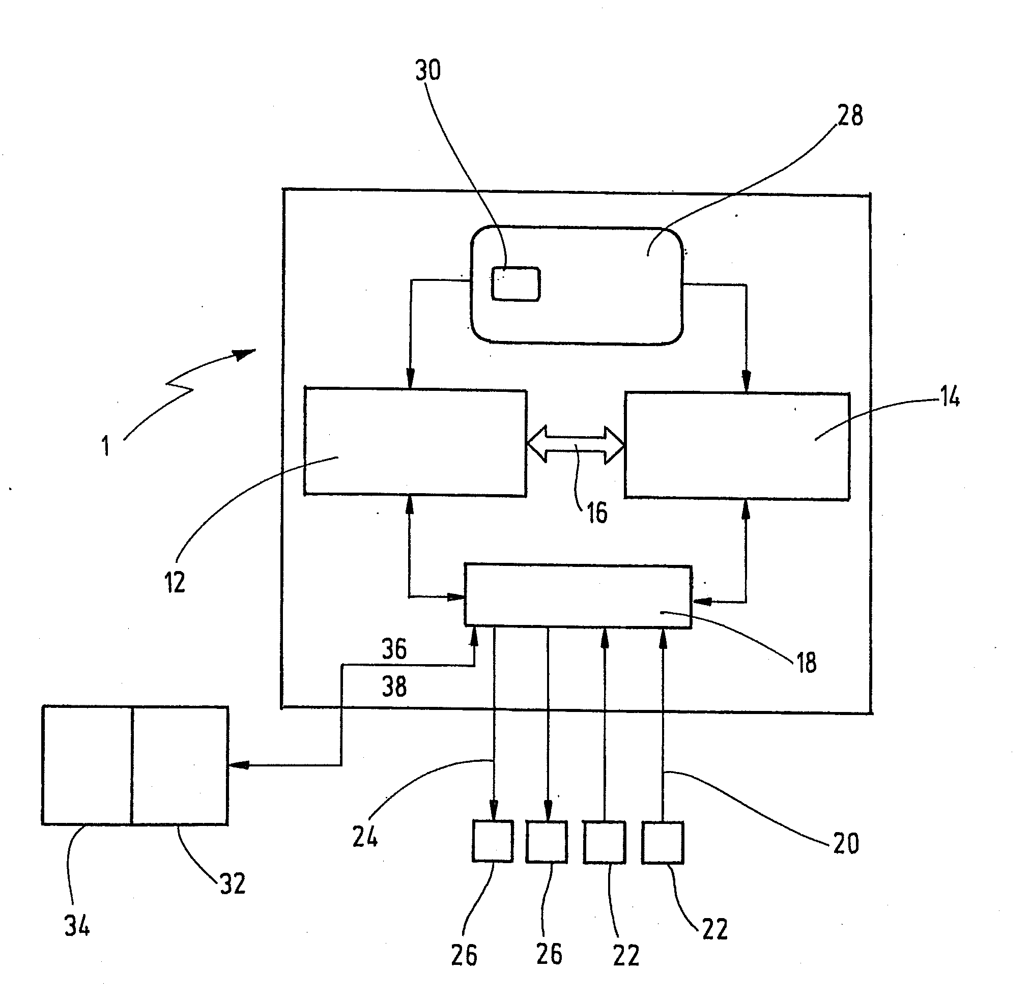
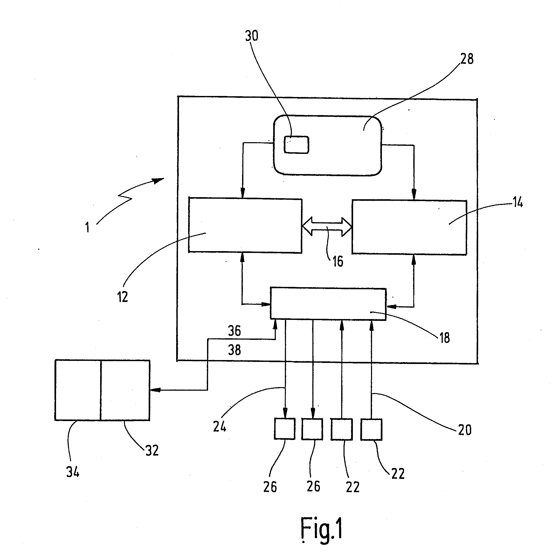
[0028]In FIG. 1, a safety controller which is designed to hold a data storage medium is denoted by the reference numeral 1 as a whole.

[0029]The safety controller 1 is of two-channel redundant design in order to achieve the requisite failsafety for controlling safety-critical processes. To represent the two-channel design, FIG. 1 shows two separate processors 12, 14 which are connected to one another by means of a bidirectional communication interface 16 in order to be able to monitor one another and interchange data. Preferably, the two channels of the safety controller 1 and the two processors 12, 14 are of a different design in order to prevent systematic faults.

[0030]The reference numeral 18 denotes an input / output unit which is connected to each of the two processors 12, 14. The input / output unit picks up input signals 20 from external sensors 22 and forwards them in an adapted data format to each of the two processors 12, 14. In addition, the input / output unit takes the process...


PUM


Abstract

A data storage medium has a carrier element configured to carry a memory element. The memory element stores data for configuring or even programming a safety controller. The data storage medium has at least one mounting element which is able to move relative to the carrier elements such that it is able to interact with a holding unit arranged on the safety controller. As a result, the data storage medium can be easily and removably be connected to the safety controller.

Description

CROSS REFERENCES TO RELATED APPLICATIONS[0001]This application is a continuation of international patent application PCT / EP2009 / 005939 filed on Aug. 17, 2009 designating the U.S., which international patent application has been published in German language and claims priority from German patent application DE 10 2008 047 514.9 filed on Sep. 12, 2008. The entire contents of these prior applications are incorporated herein by reference.BACKGROUND OF THE INVENTION[0002]The present invention relates to a safety controller for failsafely controlling a hazardous machine, and more particularly to such a safety controller having a removable data storage medium.[0003]A safety controller within the context of the present invention is an apparatus or an arrangement which receives input signals supplied by sensors and produces output signals by means of logic combinations and potentially further signal or data processing steps. The output signals are supplied to actuators, which effect specific...

Claims


Application Information

Patent Timeline
Patent Type & Authority Applications(United States)
IPC IPC(8): G05B9/02
CPCH05K5/0208G05B19/12
Inventor DICKHOFF, ROLFRINK, JOACHIM
Owner PILZ (COMPANY)
Why Eureka
Try Eureka