
Multi-column electron beam lithography apparatus and electron beam trajectory adjustment method for the same

a multi-column electron beam and electron beam technology, applied in the direction of beam deviation/focusing by electric/magnetic means, instruments, mass spectometers, etc., can solve the problems of inability to accurately apply the electron beam to the accurate position, calculation of such correction data requires time and effort, and additional time, etc., to achieve efficient electron beam trajectory adjustment

Inactive Publication Date: 2011-08-25
ADVANTEST CORP
View PDF9 Cites 14 Cited by
  • Summary
  • Abstract
  • Description
  • Claims
  • Application Information

AI Technical Summary

Benefits of technology

[0013]The present invention has been made in view of the above-described problems in the conventional art. An object of the present invention is to provide a multi-column electron beam lithography apparatus and an electron beam trajectory adjustment method which are capable of efficiently adjusting an electron beam trajectory.
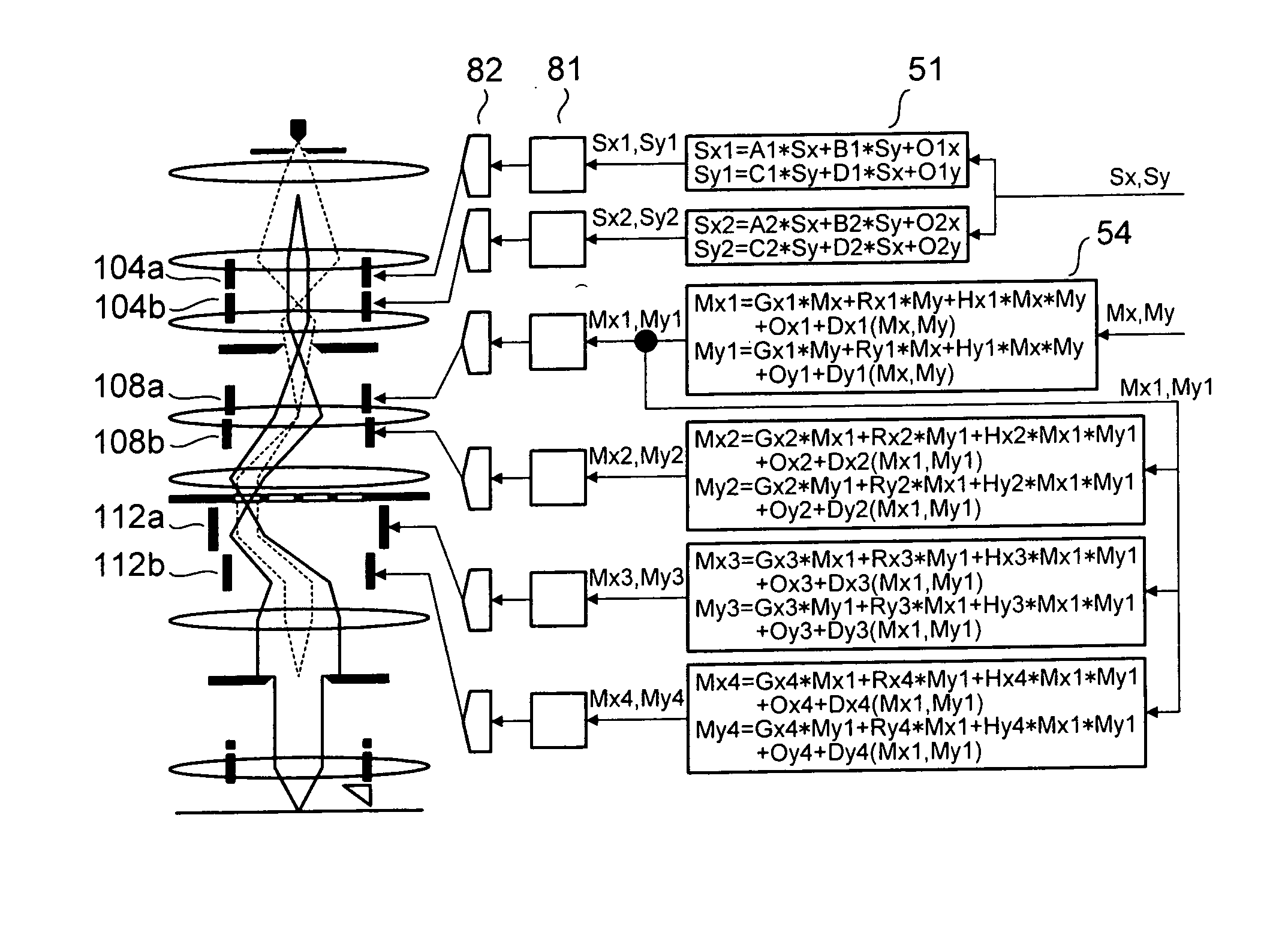
[0015]According to the embodiment, there is provided the multi-column electron beam lithography apparatus, wherein each of the columns further may include: a variable shaping unit provided upstream of the selective deflector and configured to shape a cross section of the electron beam; and a reflected electron detector configured to detect a quantity of electrons reflected from the sample due to irradiation with the electron beam, wherein the electron beam trajectory adjustment unit may include: a mask deflection data correction operation section connected to the selective and bending back deflectors, and configured to correct data on a deflection position on the stencil mask; a mask scan data generation section connected to the mask deflection data correction operation section, and configured to generate data to scan the stencil mask with the electron beam; and a scan waveform analysis section configured to accumulate a reflected electron signal of the reflected electron detector and to analyze a waveform of the reflected electron signal, and without the stencil mask installed, the electron beam trajectory adjustment unit causes the variable shaping unit to shape the electron beam in such a manner as to allow the electron beam to have a cross section smaller than a mark pattern provided on the sample; causes the selective deflector to deflect the electron beam in a plurality of different directions and causes the bending back deflector to bend back each of the electron beams deflected in the plurality of different directions; applies and scans the electron beam onto the mark pattern provided on the sample to detect a position of the mark pattern; and adjusts the deflection efficiencies of the selective and bending back deflectors in such a manner as to allow all the detected positions of the mark pattern to be detected at the same position.
[0016]According to the embodiment, there is provided the multi-column electron beam lithography apparatus wherein with the stencil mask installed, the electron beam trajectory adjustment unit may cause the variable shaping unit to shape the electron beam into a beam having a cross section smaller than each of aperture mark patterns for electron beam trajectory adjustment formed on the stencil mask; for each of the multiple aperture mark patterns for electron beam trajectory adjustment formed on the stencil mask, may scan the resultant electron beam based on data generated to allow the electron beam to scan and pass through the aperture mark pattern, and may calculate a positional relationship between the data and the aperture mark pattern for electron beam trajectory adjustment on the stencil mask, on the basis of information on electrons reflected from the target; and may determine the deflection efficiency of the selective deflector to allow the electron beam to select any aperture pattern from all the aperture patterns of the stencil mask.
[0019]In the multi-column electron beam lithography apparatus and the electron beam trajectory adjustment method according to the present invention, the deflection efficiency of the deflector involved in the selection of a pattern on the stencil mask is adjusted in a step before the installation of the stencil mask so that the electron beam deflected in any direction before being bent back may be applied to the same position. Further, after the installation of the stencil mask, the deflection efficiency of the selective deflector involved in the selection of the pattern is adjusted so that the pattern on the stencil mask can be accurately selected. This eliminates the necessity of calculating correction data individually for each of the patterns on the stencil mask, and enables efficient electron beam trajectory adjustment.

Problems solved by technology

However, even when an electron beam is applied after the signals to be applied to deflectors are determined in accordance with exposure data, the electron beam may not be applied to an accurate position sometimes depending on the deflection efficiencies of the deflectors.
However, the calculation of such correction data requires much time and effort.
This requires additional time to calculate correction data, and consequently causes a decrease in exposure throughput.

Method used


Image

  • Multi-column electron beam lithography apparatus and electron beam trajectory adjustment method for the same
  • Multi-column electron beam lithography apparatus and electron beam trajectory adjustment method for the same
  • Multi-column electron beam lithography apparatus and electron beam trajectory adjustment method for the same

Examples


Embodiment Construction

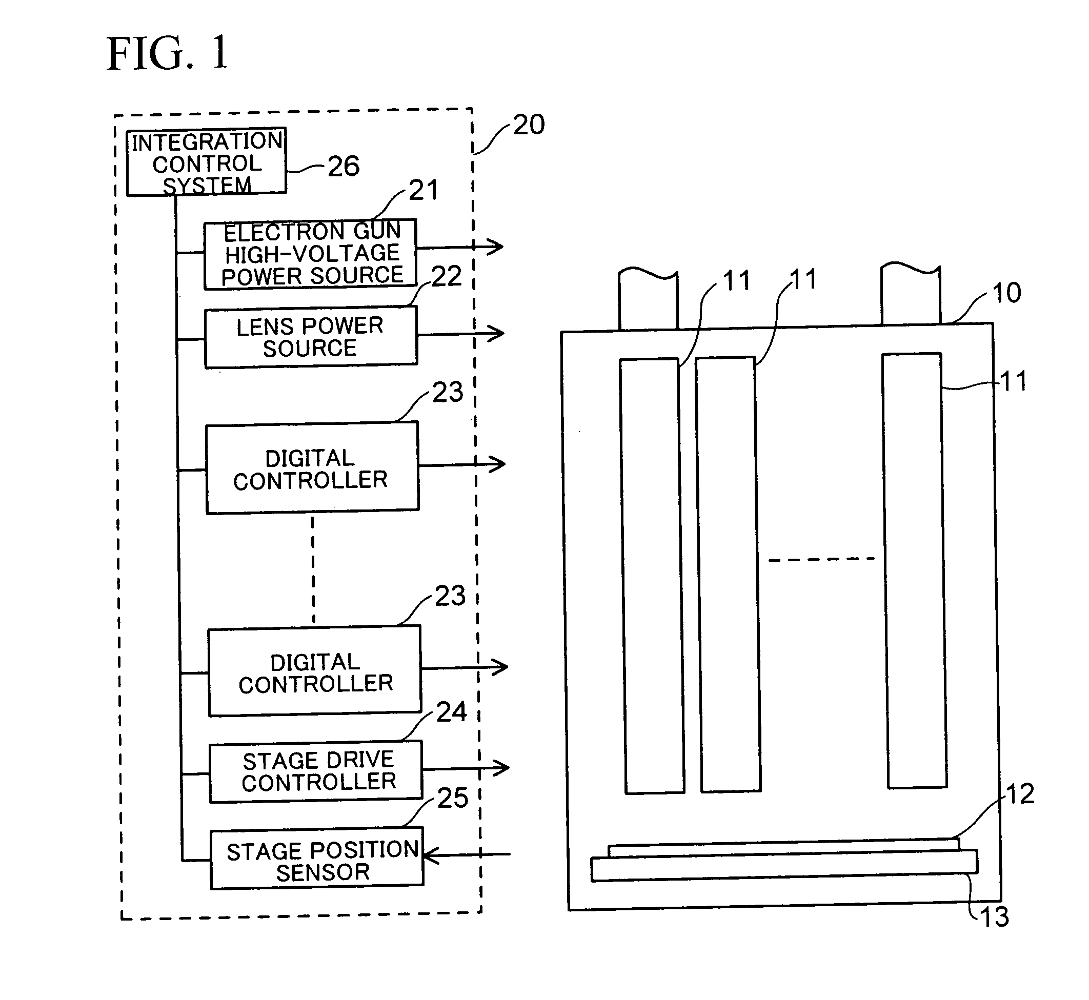
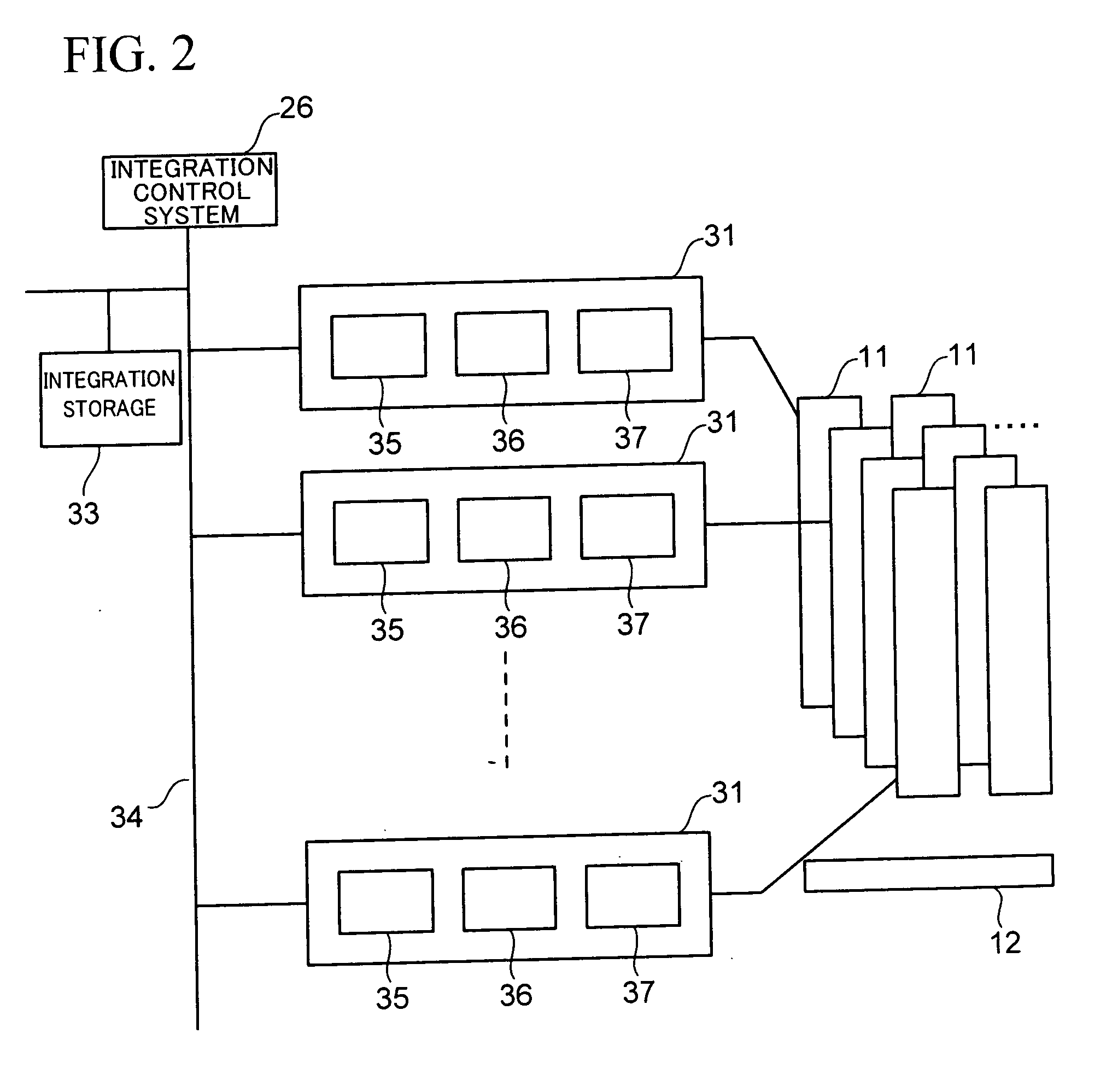
[0031]Hereinafter, an embodiment of the present invention is described with reference to the drawings. In this embodiment, a multi-column electron beam exposure apparatus is described as one example of an electron beam lithography apparatus. First, the configuration of the multi-column electron beam exposure apparatus is described with reference to FIGS. 1 to 3. Next, the configuration of this apparatus and a technique to adjust an electron beam trajectory is described with reference to FIGS. 4 to 8. Then, an electron beam trajectory adjustment method is, described with reference to FIGS. 9 to 11.

[0032](Configuration of Main Unit of Multi-Column Electron Beam Exposure Apparatus)

[0033]FIG. 1 is a schematic diagram showing the configuration of the multi-column electron beam exposure apparatus according to this embodiment.

[0034]The multi-column electron beam exposure apparatus is broadly divided into an electron beam column 10 and a controller 20 to control the electron beam column 10....


PUM


Abstract

A multi-column electron beam lithography apparatus includes multiple columns, each including a mask having several aperture patterns; a selective deflector to deflect an electron beam to select an aperture pattern; a bending back deflector to bend the beam passed through the pattern back to the column optical axis; and an electron beam trajectory adjustment unit to adjust deflection efficiencies of the deflectors without the mask installed to allow the beam deflected toward any positions in a deflection region to be bent back and applied to the same position on a sample, and to adjust the deflection efficiency of the selective deflector with the mask installed to allow the beam to be deflected toward any pattern of the mask, while maintaining a relationship between the deflection efficiencies.

Description

CROSS-REFERENCE TO THE RELATED ART[0001]This application is a continuation of prior International Patent Application No. PCT / JP2009 / 055067, filed Mar. 16, 2009, the entire contents of which are incorporated herein by reference.BACKGROUND OF THE INVENTION[0002]1. Field of the Invention[0003]The present invention relates to a multi-column electron beam lithography apparatus and an election beam trajectory adjustment method for the same. In particular, the present invention relates to a multi-column electron beam lithography apparatus capable of efficiently and accurately selecting one of character projections formed in respective masks of multiple columns, and to an electron beam trajectory adjustment method for the same.[0004]2. Description of the Prior Art[0005]For the purpose of improving throughput, an electron beam exposure apparatus, which is a typical example of an electron beam lithography apparatus, is provided with a variable rectangular opening or a plurality of stencil mas...

Claims


Application Information

Patent Timeline
IPC IPC(8): H01J3/26H01J37/29
CPCB82Y10/00B82Y40/00H01J37/3023H01J2237/30472H01J37/3177H01J2237/15H01J2237/30461H01J37/3174
Inventor YAMADA, AKIOYABE, TAKAYUKI
Owner ADVANTEST CORP
Learn More