
Replaceable insert for a hammermill hammer

a hammer and insert technology, applied in the field of power equipment, can solve the problems of reducing the shard affecting the shard size of the hammer, and affecting the shard size of the hammer, and achieve the effect of simple and fast, and reducing the shard siz

Inactive Publication Date: 2011-08-25
CRAVEN MATT H
View PDF18 Cites 9 Cited by
  • Summary
  • Abstract
  • Description
  • Claims
  • Application Information

AI Technical Summary

Benefits of technology

[0011]The replaceable insert enables the hammermill operator to reverse or replace the insert in the hammer shank without disassembling the hammermill to remove the hammer shank from its retaining rod. The operator need only position the hammer shank having the worn or damaged insert so that it is accessible, unbolt the worn or damaged insert from its hammer shank, and either reverse the insert to expose a fresh leading or cutting surface or install a new insert. Thus, a hammer shank can be repaired very simply and quickly with the removal and installation of a single bolt, rather than having to at least partially disassemble the hammermill to replace the entire hammer shank.

Problems solved by technology

The hammers are thrown outwardly during high speed rotation of the machine due to centrifugal effect, with their masses resulting in the shredding and pulverizing of the material being processed.
While carbide is extremely hard and resistant to wear, it is relatively brittle and often cracks or breaks away from the base metal to which it has been welded.
Moreover, such conventional hammer shanks are generally not symmetrical, i.e., they cannot be removed from their rods and turned around 180° to exchange the leading and trailing edges to provide a fresh leading or cutting edge.
When such conventional hammer shanks are worn or damaged, they must be discarded after removal and replaced with a new hammer shank.

Method used


Image

  • Replaceable insert for a hammermill hammer
  • Replaceable insert for a hammermill hammer
  • Replaceable insert for a hammermill hammer

Examples


Embodiment Construction

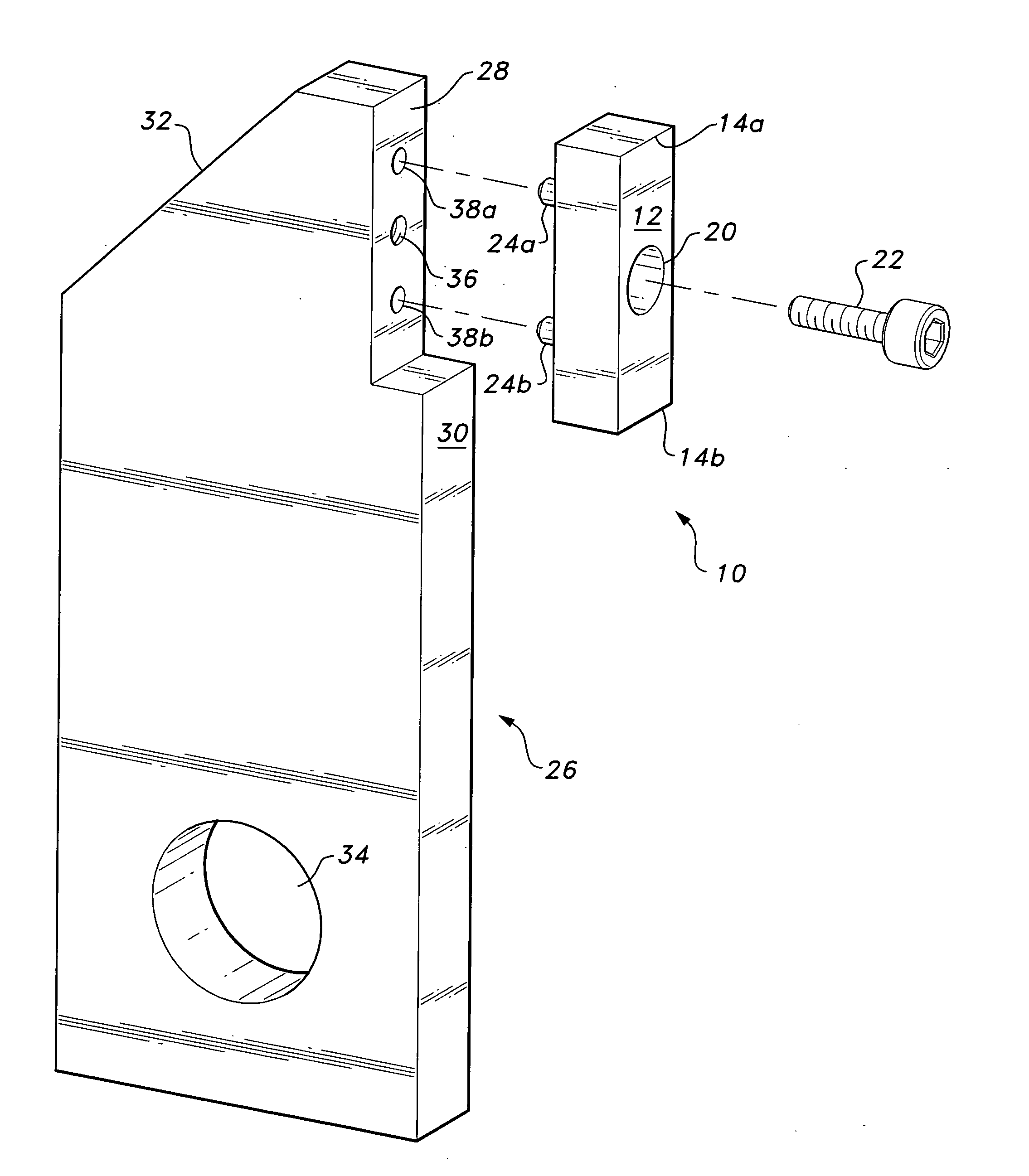
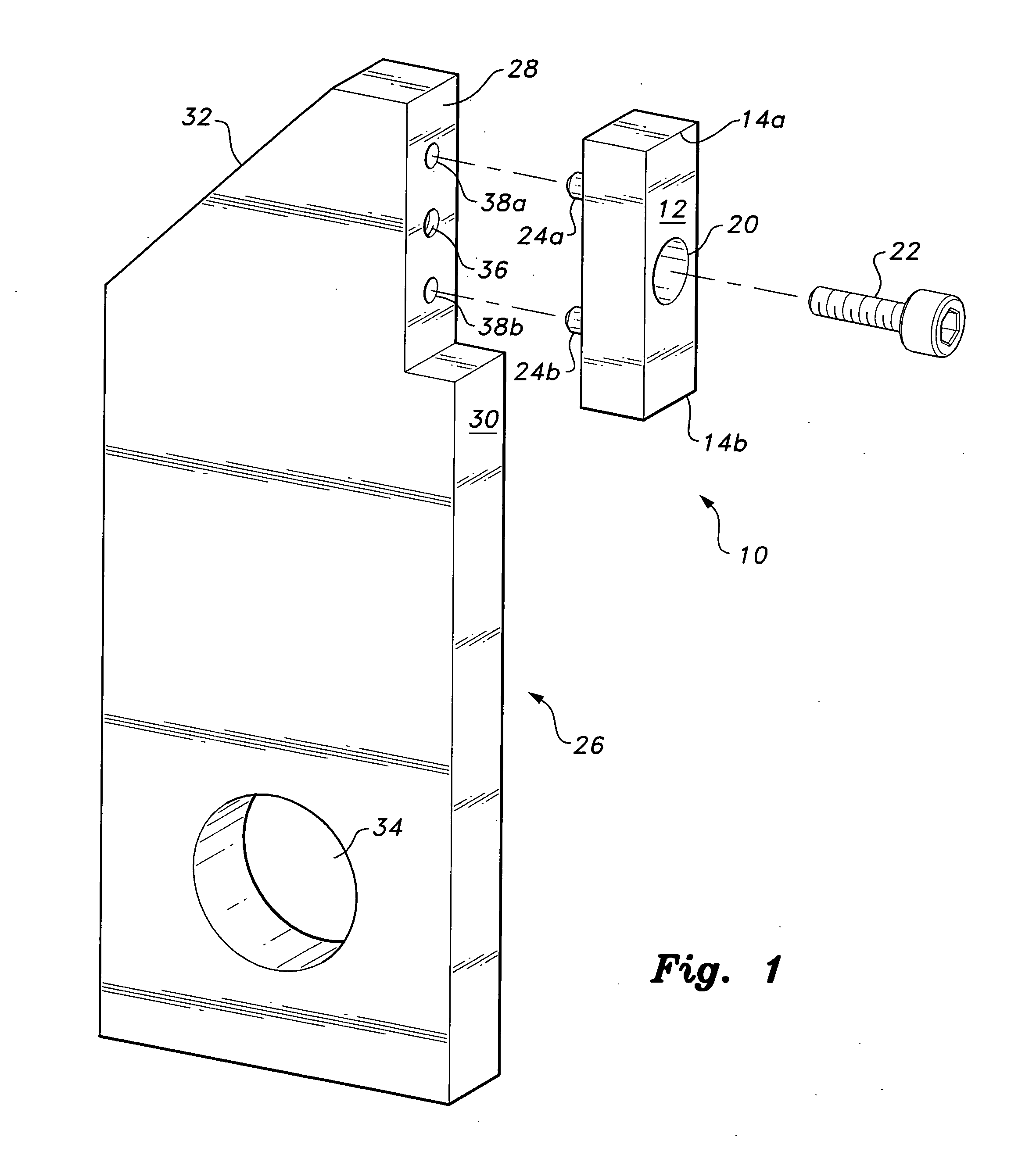
[0017]The replaceable insert for a hammermill hammer is attachable to the hammer or hammer shank of a powered hammermill, as used in the shredding, pulverizing, and / or comminuting of various materials. The replaceable insert and its specially configured hammer or hammer shank allow the insert to be replaced when worn or damaged without requiring partial disassembly of the hammermill to remove the entire hammer or shank.

[0018]FIGS. 1 and 2 respectively provide an exploded perspective view and a side elevation view in section of the hammer and insert or block, with FIG. 3 being a front elevation view of the insert. The insert block 10 is formed of a hard metal or metal alloy, e.g., tool steel, high carbon steel, carbide or carbide alloys, tungsten, or tungsten alloys, or other hard metals or alloys as desired. More ductile metals are preferably used, in order to reduce or preclude cracking, chipping, and fracturing that often occur with more brittle materials.

[0019]The insert block 10...


PUM


Abstract

The replaceable insert for a hammermill hammer enables the insert to be removed and replaced by the removal and installation of a single bolt in the leading face or edge of the hammer, rather than requiring partial disassembly of the hammermill for the removal of a damaged hammer and hammer shank from its retaining rod. The insert is formed of hard and tough metal, e.g., tool steel, carbide alloy, etc., as a longitudinally and laterally symmetrical rectangular parallelepiped, the hammer shank having a cooperating relief formed therein. The symmetrical configuration allows the insert to be reversed through 180° in its installation, thereby exposing a fresh insert face after the first face has been worn or damaged. A pair of indexing pins extends from the insert, the pins fitting closely within cooperating receptacles in the hammer shank relief to secure the insert precisely within the relief.

Description

BACKGROUND OF THE INVENTION[0001]1. Field of the Invention[0002]The present invention relates generally to power equipment used for the shredding, pulverizing, and comminuting of material, and particularly to a replaceable insert for a hammer as used in powered hammermills and the like.[0003]2. Description of the Related Art[0004]Hammermills have been used for a considerable time for shredding, pulverizing, and comminuting a wide range of different types of materials. Such machines are used for shredding metal for recycling, pulverizing nuts, grains, and other food products in food processing, shredding and breaking up woody materials for use as mulch, and innumerable other purposes and operations.[0005]Hammermills are generally constructed with a plurality of axially parallel shafts that rotate around a central axis, with each shaft having a plurality of hammers or hammer shanks pivotally installed thereon. The hammers are thrown outwardly during high speed rotation of the machine ...

Claims


Application Information

Patent Timeline
IPC IPC(8): B02C13/28
CPCB02C13/28
Inventor CRAVEN, MATT H.
Owner CRAVEN MATT H
Learn More