
Air spring system

a technology of air springs and springs, which is applied in the direction of shock absorbers, pumping plants, transportation and packaging, etc., can solve the problems of unnecessary system replenishment, and achieve the effect of simple construction and economic production

Active Publication Date: 2011-08-25
DR ING H C F PORSCHE AG
View PDF9 Cites 3 Cited by
  • Summary
  • Abstract
  • Description
  • Claims
  • Application Information

AI Technical Summary

Benefits of technology

[0004]It is an object of the invention to provide an air spring system which is of simple construction and can be produced economically.
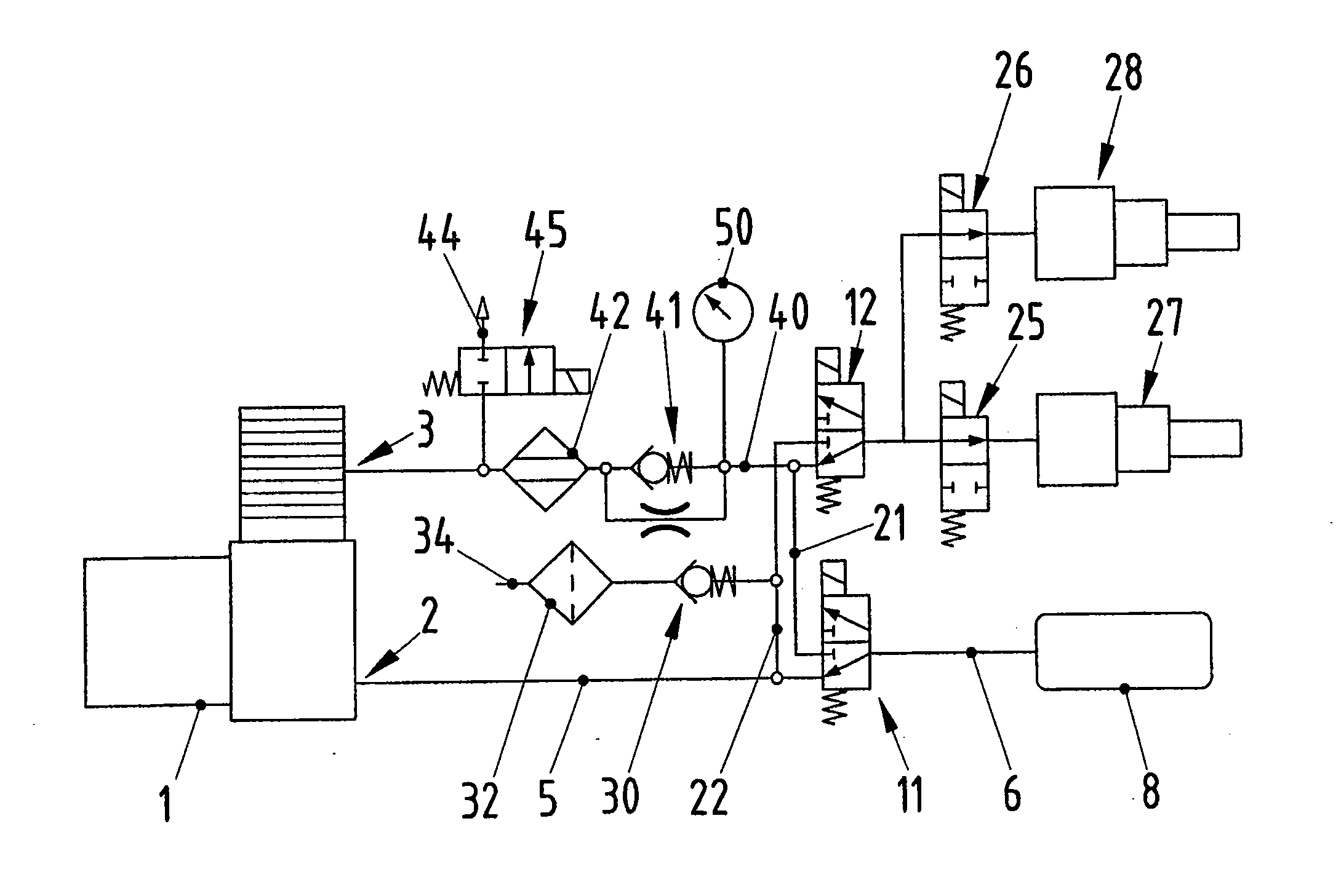
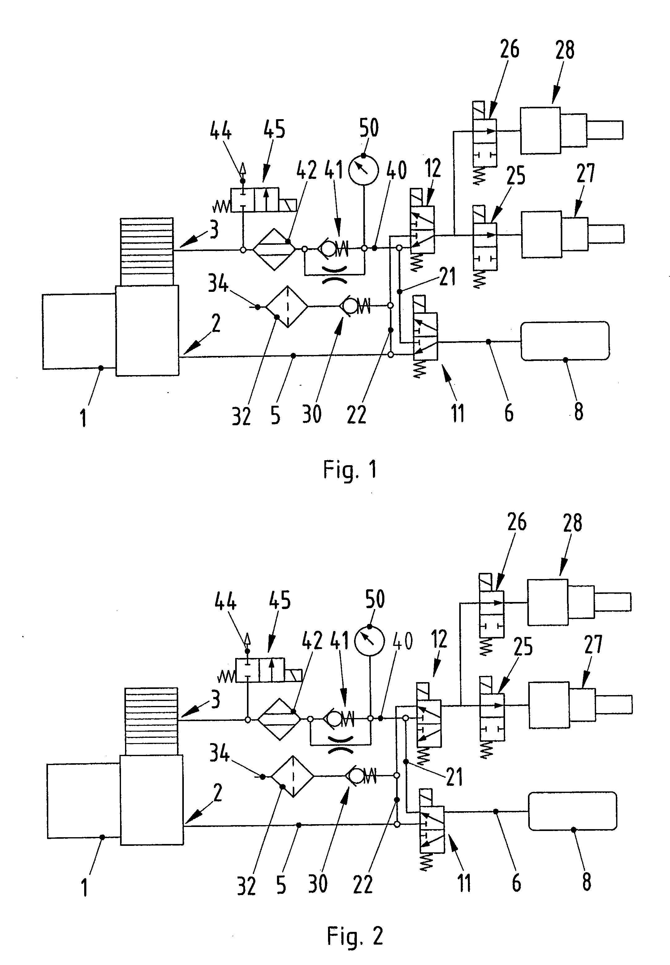
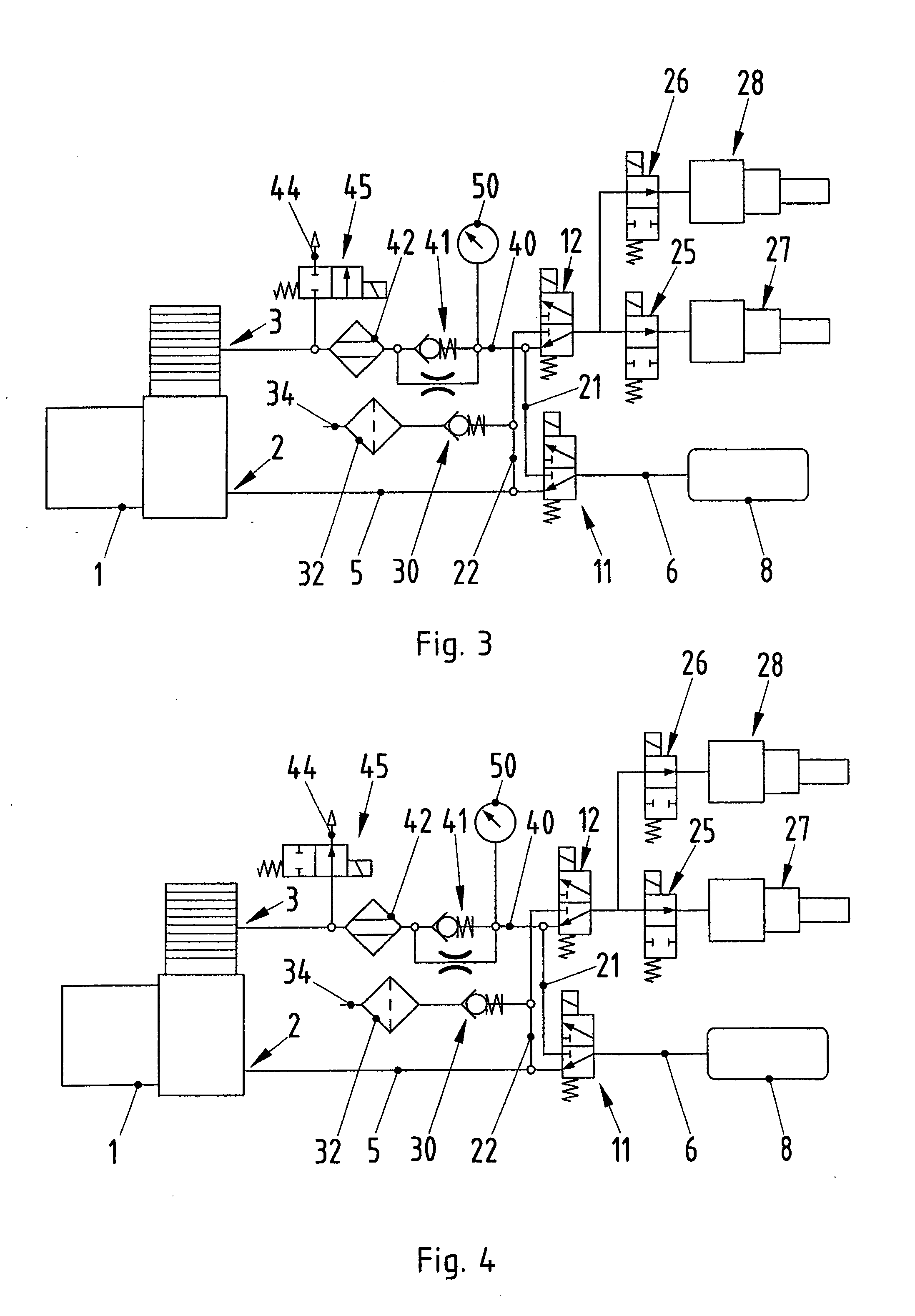
[0005]This object is achieved in an air spring system having a compressor, which has a suction side and a delivery side, having a pressure reservoir and having a first valve device and a second valve device, which are connected between the compressor and the pressure reservoir, in that the first valve device and the second valve device are each embodied as 3 / 2-way valves. The use in accordance with the invention of the 3 / 2-way valves makes possible a simple pneumatic circuit. The arrangement in accordance with the invention of the 3 / 2-way valves enables the motor vehicle to be raised directly, even when the air spring system is empty. This provides the advantage that it is not necessary to fill the pressure reservoir before raising the motor vehicle, thereby considerably shortening unwanted waiting times.
[0010]Another preferred illustrative embodiment of the air spring system is characterized in that the second valve connecting line is connected to an intake line via a check valve. An air filter can be arranged in the intake line. The check valve allows air to be drawn in from the environment and prevents unwanted escape of air from the air filter system into the environment.
[0013]Another preferred illustrative embodiment of the air spring system is characterized in that a one-way restrictor device and an air drier are connected in series between the first valve connecting line and the delivery side of the compressor. In the one-way restrictor device, a check valve and a restrictor are connected in parallel. The check valve prevents air from flowing back to the return side of the compressor in an unrestricted way. A check valve can be connected between the one-way restrictor device and the air drier, preventing unwanted backflow through the drier.

Problems solved by technology

Owing to leaks, it may be necessary to replenish the system with air from outside, even in a closed air spring system.

Method used


Image

  • Air spring system
  • Air spring system
  • Air spring system

Examples


Embodiment Construction

[0018]In FIGS. 1 to 9, different illustrative embodiments and states of an air spring system according to aspects of the invention are shown in the form of pneumatic circuit diagrams. The air spring system comprises a compressor 1 with a suction side 2 and a delivery side 3. The suction side 2 of the compressor 1 can be connected to a pressure reservoir 8 via lines 5, 6. Lines 5, 6 are pneumatic lines, as are further lines described below.

[0019]A first valve device 11 is connected between the suction side 2 of the compressor 1 and the pressure reservoir 8. The first valve device 11 is embodied as a 3 / 2-way valve. Lines 5 and 6 are connected to two ports of the first valve device 11. A first valve connecting line 21 is connected to the third port of the first valve device 11. Via the first valve connecting line 21, the first valve device 11 is connected to a second valve device 12.

[0020]The second valve device 12 is likewise embodied as a 3 / 2-way valve. Connected to the second valve ...


PUM


Abstract

An air spring system is disclosed. The air spring system has a compressor, which has a suction side and a delivery side, a pressure reservoir, a first valve device and a second valve device. Each valve device is connected between the compressor and the pressure reservoir. In order to provide the air spring system, which is of simple construction and can be produced economically, the first valve device and the second valve device are each embodied as 3 / 2-way valves.

Description

CROSS REFERENCE TO RELATED APPLICATION[0001]This U.S. patent application claims priority to German Patent Application DE 10 2010 008748.3, filed Feb. 20, 2010, which is incorporated by reference herein in its entirety.FIELD OF THE INVENTION[0002]The invention relates to an air spring system having a compressor, which has a suction side and a delivery side, having a pressure reservoir and having a first valve device and a second valve device, which are connected between the compressor and the pressure reservoir. The invention furthermore relates to a motor vehicle having an air spring system of this kind.BACKGROUND OF THE INVENTION[0003]Air spring systems operate either with a closed or an open control loop. In the case of open air spring systems, air is drawn in from the environment by a compressor and delivered to air springs of a motor vehicle in order to raise the motor vehicle. For discharge, the air is discharged to the environment, for example. It is possible here to use a pre...

Claims


Application Information

Patent Timeline
IPC IPC(8): E03B11/16
CPCB60G17/0523B60G17/052Y10T137/85978
Inventor SPRENGEL, THOMASBLATTNER, CLAUS
Owner DR ING H C F PORSCHE AG
Learn More