
Quasi-solid-state photoelectrochemical solar cell formed using inkjet printing and nanocomposite organic-inorganic material

a photoelectrochemical and solar cell technology, applied in the direction of solid-state devices, capacitors, electrolytic capacitors, etc., can solve the problems of wasting an important part of the surface of the cell, reducing the efficiency of the cell, and reducing the quantity of adsorbed organic photosensitizers. , to achieve the effect of increasing the quantity of organic photosensitizers and increasing the overall efficiency of the cell

Inactive Publication Date: 2011-08-25
BRITE HELLAS
View PDF44 Cites 4 Cited by
  • Summary
  • Abstract
  • Description
  • Claims
  • Application Information

AI Technical Summary

Benefits of technology

[0007]The invention is directed to methods and apparatus involving a quasi-solid-state cell comprising a multilayer film, based on nanocomposite organic-inorganic materials. The nanocomposite organic-inorganic materials may be synthesized, for instance, by purely chemical processes and deposited by various techniques including inkjet-printing under ambient conditions. In particular, the invention involves formation of a cell using novel processes for the synthesis and deposition of titanium dioxide (“TiO2” or “titania”). In accordance with aspects of the invention, an active surface area of a TiO2 film is increased, which accordingly increases the quantity of adsorbed organic photosensitizer and increases overall efficiency of the cell.
[0008]An increase in efficiency also may be achieved by using a solid gel electrolyte having electric conductivity-enhancing components incorporated in the electrolyte. The solid gel electrolyte may provide several advantages, including that it may obviate the need to separately seal the cell because it is self-sealing, which greatly decreases cell assembly cost. Separate sealing materials not only add to materials and assembly costs, but they waste an important part of the surface of the cell, thus decreasing cell active surface. The embodiments of invention may make optimal use of cell surface since no parts are covered by sealing materials.
[0009]Finally, an exemplary gel electrolyte may be very thin, much thinner than electrolyte layers in previous art cells. The thickness of the gel electrolyte, according to cross-sectional images, varies from about 50 to about 80 micrometers, depending to its contents. Therefore, ohmic losses are lower in cells formed in accordance with embodiments of the invention.

Problems solved by technology

Separate sealing materials not only add to materials and assembly costs, but they waste an important part of the surface of the cell, thus decreasing cell active surface.

Method used


Image

  • Quasi-solid-state photoelectrochemical solar cell formed using inkjet printing and nanocomposite organic-inorganic material
  • Quasi-solid-state photoelectrochemical solar cell formed using inkjet printing and nanocomposite organic-inorganic material
  • Quasi-solid-state photoelectrochemical solar cell formed using inkjet printing and nanocomposite organic-inorganic material

Examples


example 1

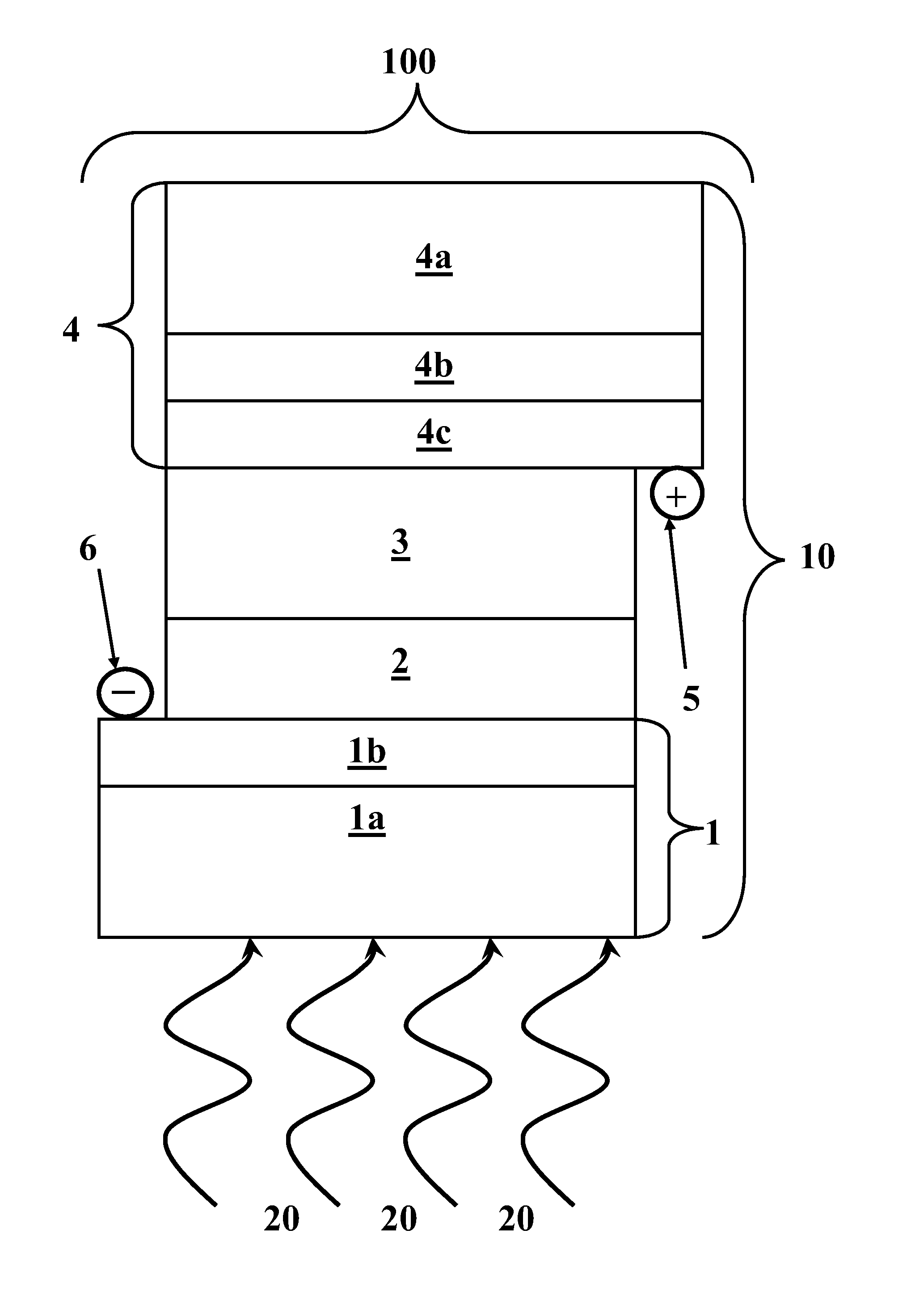
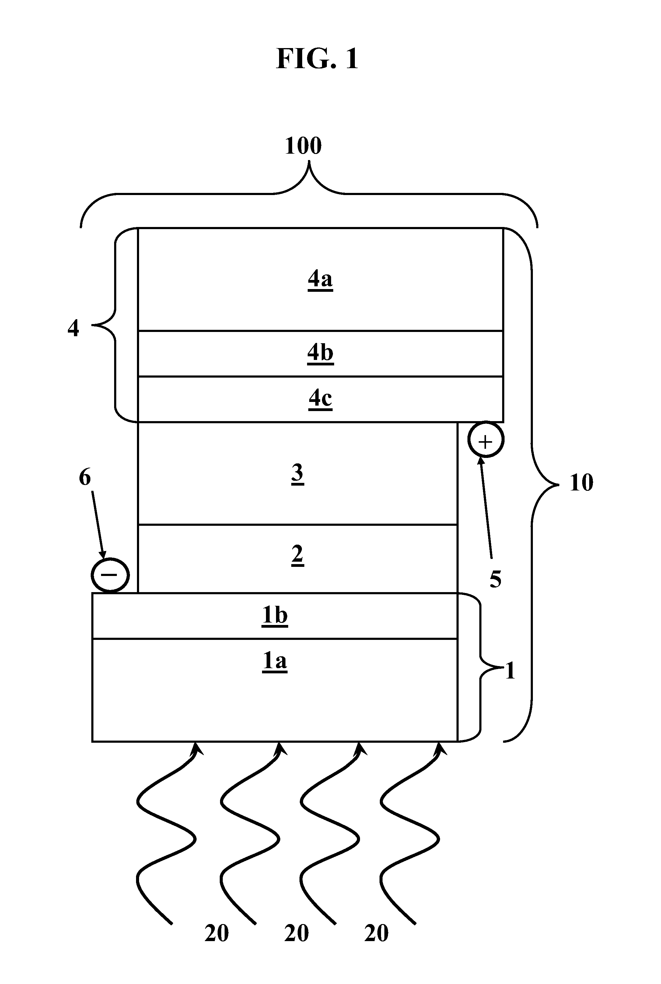
[0048]A first exemplary PECSC 100 was formed comprising the following layer stack 10. A glass plate 1a bearing a SnO2:F layer 1b was used as negative electrode 1 and as a substrate for deposition of titania film 2. Positive electrode 4 included a glass plate 4a bearing a SnO2:F layer 4b as a substrate for deposition of a thin layer 4c of platinum. Positive electrode 4 included a semi-transparent Pt layer 4c of a thickness of about 200 nm formed by spin-casting of an isopropanol solution of hexachloroplatinic acid.

[0049]On negative electrode 1, a colloidal solution was deposited from which titania film 2 was produced after calcination. The colloidal solution was made as follows: about 3 g ethanol (“EtOH”) were mixed with about 0.71 g Triton X-100. Then, about 0.64 g AcOH and about 0.36 g titanium isopropoxide were added under vigorous stirring and ambient conditions. After about 30 minutes of stirring, approximately one drop of this colloidal solution was placed on negative electrode...

example 2

[0053]A PECSC was formed with the same components as that of Example 1, using the same proportions of the employed reagents and the same methods of preparation, with the exception that, in preparation of solid gel 3, propylene carbonate was replaced with an approximately 1:1 mixture of propylene carbonate and ethylene carbonate. Under illumination by simulated solar radiation of about 100 mW / cm2, PECSC of Example 2 produced about 11.6 mA / cm2 short circuit current, about 0.62 volts of open circuit voltage, a fill factor of about 0.69, and an overall efficiency of about 5.0%.

example 3

[0054]A PECSC was formed with the same components as that of Example 1, using the same proportions of the employed reagents and the same methods of preparation, with the exception that, in preparation of solid gel 3, propylene carbonate was replaced with poly(ethylene glycol)-200. When illuminated by simulated solar radiation of about 100 mW / cm2, PECSC of Example 3 produced about 12.4 mA / cm2 short circuit current, about 0.61 volts of open circuit voltage, a fill factor of about 0.7, and an overall efficiency of about 5.3%.


PUM


Abstract

Methods and apparatus are disclosed regarding photoelectrochemical solar cells formed using inkjet printing and nanocomposite organic-inorganic materials, such as for converting solar energy into electricity. An exemplary solid photoelectrochemical solar cell formation includes thin layers of nanocomposite organic-inorganic materials. A specific exemplary solid photoelectrochemical solar cell may include: a negative electrode comprising a transparent electroconductive glass plate; a thin transparent film of mesoporous nanocrystalline titanium dioxide of controlled thickness above the negative electrode, formed by dip-coating, spin-coating or inkjet printing, and having a photosensitizer dye comprising a ruthenium organometallic complex, a merocyanine dye, or a hemicyanine dye; a layer of a solid gel electrolyte formed above the titanium dioxide layer and including a nanocomposite organic-inorganic material and a redox couple; and a positive electrode comprising a second electroconductive glass plate having a thin layer of deposited electrocatalyst made of platinum, carbon, or both, in the form of nanostructures, including nanoparticles, nanotubes, conjugated conductive polymers, or their mixtures.

Description

CROSS REFERENCE TO RELATED APPLICATION[0001]This application is related to and claims the benefit of U.S. Provisional Patent Application Ser. No. 61 / 306,546 (“the '546 application”), titled “Photoelectrochemical Solar Cell Including Nanocomposite Organic-Inorganic Materials,” and filed Feb. 22, 2010, which is incorporated by reference herein in its entirety for all purposes.STATEMENT REGARDING SPONSORSHIP OF DEVELOPMENT[0002]Aspects of the invention described herein are the result of development co-financed by Hellenic Funds and by the European Regional Development Fund (ERDF) under the Hellenic National Strategic Reference Framework (NSRF) 2007-2013, according to contract MICRO2-32 of the project “Development of Semitransparent Solar Panels” within the Program “Hellenic Technology Clusters in Microelectronics-Phase-2 Aid Measure.”BACKGROUND OF THE INVENTION[0003]1. Field of the Invention[0004]The invention relates to methods and apparatus of a Photoelectrochemical Solar Cell (“PECS...

Claims


Application Information

Patent Timeline
Patent Type & Authority Applications(United States)
IPC IPC(8): H01L31/0264H01L31/18
CPCH01G9/2009H01G9/2031Y02E10/549H01L51/0005Y02E10/542H01G9/2059H10K71/135
Inventor LIANOS, PANAGIOTISSTATHATOS, ELIAS
Owner BRITE HELLAS
Learn More