Dye-sensitized solar cell and dye-sensitized solar cell module

Inactive Publication Date: 2011-08-18
SHARP KK
View PDF4 Cites 16 Cited by
  • Summary
  • Abstract
  • Description
  • Claims
  • Application Information

AI Technical Summary

Benefits of technology

[0018]According to the present invention, the surface of the aforementioned porous insulating layer is at least partially or entirely provided with the insulation coating portion made of the material different from that of the porous insulating layer so that the quantity of dye adsorbable per unit area is smaller than that in a porous insulating provided with no insulation coating portion in the dye-sensitized solar cell having the porous insulating layer for suppressing electron transfer from the photoelectric conversion layer to the catalyst layer between the porous semiconductor layer (photoelectric conversion layer) on which the dye is adsorbed and the catalyst layer, whereby a dye-sensitized solar cell suppressing reduction of photoelectric conversion efficiency resulting from dye adsorption on the insulating layer can be provided.

Problems solved by technology

However, the former has such a problem that the manufacturing cost for the silicon substrate is high, and the latter has such a problem that various types of semiconductor manufacturing gas and a complicated apparatus must be employed and hence the manufacturing cost is increased.
Therefore, while efforts for reducing the cost per power generation output by improving the efficiency for photoelectric conversion are continued in each solar cell, the aforementioned problems have not yet been solved.

Method used


Image

  • Dye-sensitized solar cell and dye-sensitized solar cell module
  • Dye-sensitized solar cell and dye-sensitized solar cell module
  • Dye-sensitized solar cell and dye-sensitized solar cell module

Examples


example 1

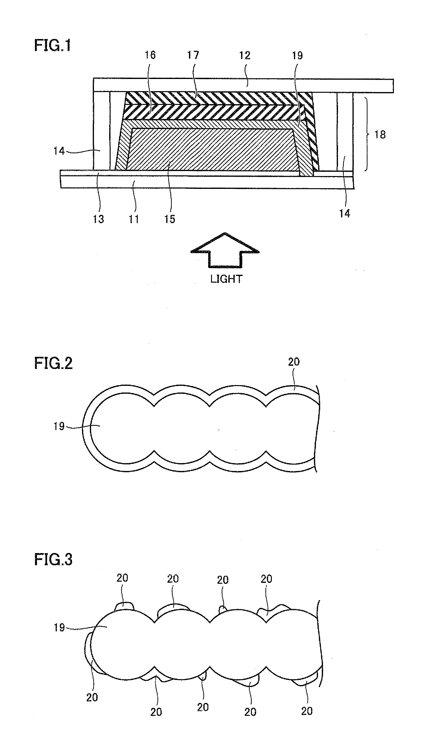
[0115]In Example 1, a dye-sensitized solar battery cell shown in FIG. 1 was prepared.

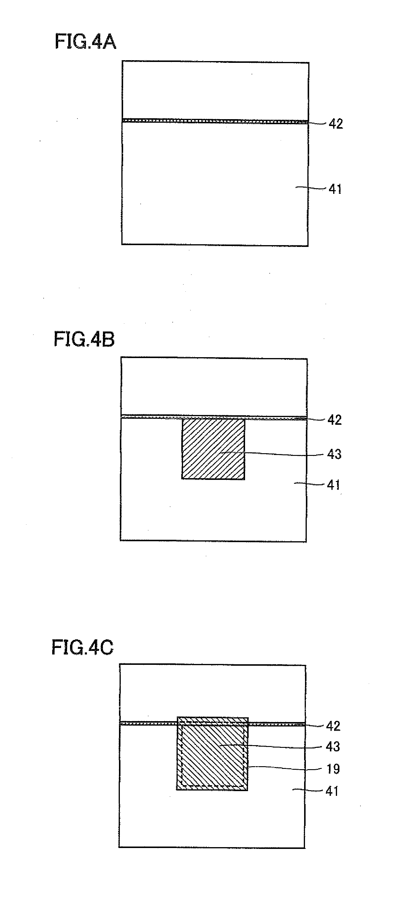
[0116]A transparent electrode substrate 41 (by Nippon Sheet Glass Co., Ltd., glass provided with SiO2 film), in which a conductive layer made of fluorine-doped tin oxide (FTO) was formed on a support body consisting of a glass substrate, was prepared. The transparent electrode substrate 41 was 30 mm by 30 mm having a thickness of 4.0 mm. As shown in FIG. 4A, the conductive layer of transparent electrode substrate 41 in which the support body and the conductive layer were stacked was cut by laser scribing, to form a scribing line 42 (FIGS. 4A to 4E are schematic diagrams in a case of observing the dye-sensitized solar cell from the upper surface). Then, commercially available titanium oxide paste (by Solaronix SA, trade name: D / SP) was applied by employing a screen plate having a pattern of a porous semiconductor layer shown in FIG. 4B and a screen printer (by Newlong Seimitsu Kogyo Co., Ltd, type nu...

example 2

[0132]A dye-sensitized solar cell was prepared by a method similar to that in Example 1 except that an insulation coating portion consisting of an Al2O3 film whose thickness was about 5 nm was formed on the overall surface of porous insulating layer 19 by employing 6 μL of a 5 weight % ethanol solution of aluminum isopropoxide (by Kishida Chemical Co., Ltd) after forming porous insulating layer 19 in Example 1, and photoelectric conversion efficiency was measured. Further, the porous zirconia membrane provided with the Al2O3 insulation coating portion was separated similarly to Example 1, and the quantity of dye adsorption on the porous insulating layer was measured. Table 1 shows the conversion efficiency and the quantity of dye adsorption in the dye-sensitized solar cell.

example 3

[0133]A dye-sensitized solar cell was prepared by a method similar to that in Example 1 except that an insulation coating layer of MgO whose thickness was about 5 nm was formed by employing 6 μL of a 5 weight % ethanol solution of magnesium ethoxide (by Kishida Chemical Co., Ltd.) after forming porous insulating layer 19 in Example 1, and photoelectric conversion efficiency was measured. Further, the porous zirconia membrane provided with the MgO insulation coating portion was separated similarly to Example 1, and the quantity of dye adsorption on the porous insulating layer was measured. Table 1 shows the conversion efficiency and the quantity of dye adsorption in the dye-sensitized solar cell.


PUM


Abstract

Disclosed are a dye-sensitized solar cell and a dye-sensitized solar cell module that suppress a decrease in photoelectric conversion efficiency caused by dye adsorption to an insulation layer. The dye-sensitized solar cell is characterized by having a stacked structure wherein an electroconductive layer, a photoelectric conversion layer formed of a porous semiconductor layer into which a dye is absorbed, a porous insulation layer, a catalyst layer, and a counter-electrode electroconductive layer are stacked in this order on a light-transmissive support body, with an insulation cover part that is comprised of a material which differs from that of the porous insulation layer formed on at least a part of or on all of the surface of the porous insulation layer.

Description

TECHNICAL FIELD[0001]The present invention relates to a dye-sensitized solar cell and a dye-sensitized solar cell module.BACKGROUND ART[0002]A solar cell capable of converting sunlight to electric power is watched with interest as an energy source substituting for fossil fuel. At present, a solar cell employing a crystalline silicon substrate and a thin-film silicon solar cell are beginning to be partially put into practice. However, the former has such a problem that the manufacturing cost for the silicon substrate is high, and the latter has such a problem that various types of semiconductor manufacturing gas and a complicated apparatus must be employed and hence the manufacturing cost is increased. Therefore, while efforts for reducing the cost per power generation output by improving the efficiency for photoelectric conversion are continued in each solar cell, the aforementioned problems have not yet been solved.[0003]As a new type of solar cell, a photoelectrochemical solar cel...

Claims


Application Information

Patent Timeline
IPC IPC(8): H01L31/042H01L31/0216H01L31/0224
CPCH01G9/2031H01G9/2036Y02E10/542H01G9/2077H01G9/2059
Inventor KOBAYASHI, SHINSUKEFUKUI, ATSUSHIKOMIYA, RYOICHI
Owner SHARP KK
Why Eureka
Try Eureka