
Porous and non-porous nanostructures and application thereof

a nanostructure and nanotechnology, applied in the direction of raney catalysts, metal/metal-oxide/metal-hydroxide catalysts, filter regeneration, etc., can solve the problems of nanoparticle handling and/or attachment, lack of porosity control in background art techniques, and affect not only luminescent applications, so as to improve the process window

Active Publication Date: 2011-08-11
RES TRIANGLE INST
View PDF20 Cites 55 Cited by
  • Summary
  • Abstract
  • Description
  • Claims
  • Application Information

AI Technical Summary

Benefits of technology

[0013]Still another feature of the invention is to promote application of using the electrospun porous and smooth polymer nanofibers as a medium to dispose nanoparticle material.
[0014]Still another feature of the invention is to promote application of the electrospun porous and smooth polymer nanofibers for lighting.
[0014]Still another feature of the invention is to promote application of the electrospun porous and smooth polymer nanofibers for lighting.
[0016]Various of these and other features are provided for in the disclosed embodiments of the invention given below.
[0017]It is to be understood that both the foregoing general description of the invention and the following detailed description are exemplary, but are not restrictive of the invention.

Problems solved by technology

One problem discussed in detail below and recognized by the inventors relates to the safety, handling, attachment, processing of nanoparticles in the luminescent device and catalysis applications.
This general problem affects not only the luminescent applications but also affects other application areas where nanoparticle handling and / or attachment to other material structures is at issue.
Other problems with the background art, which the present inventors have recognized, concern the lack of porosity control in these background art techniques.

Method used


Image

  • Porous and non-porous nanostructures and application thereof
  • Porous and non-porous nanostructures and application thereof
  • Porous and non-porous nanostructures and application thereof

Examples


Embodiment Construction

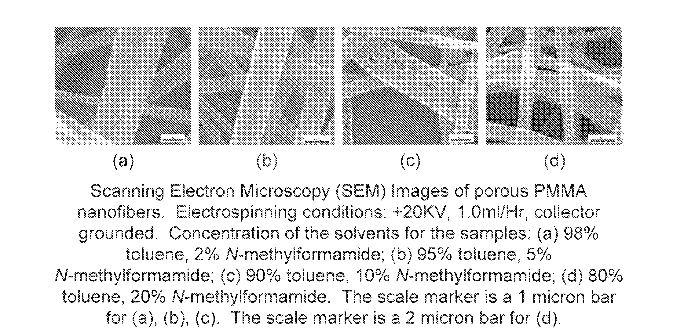
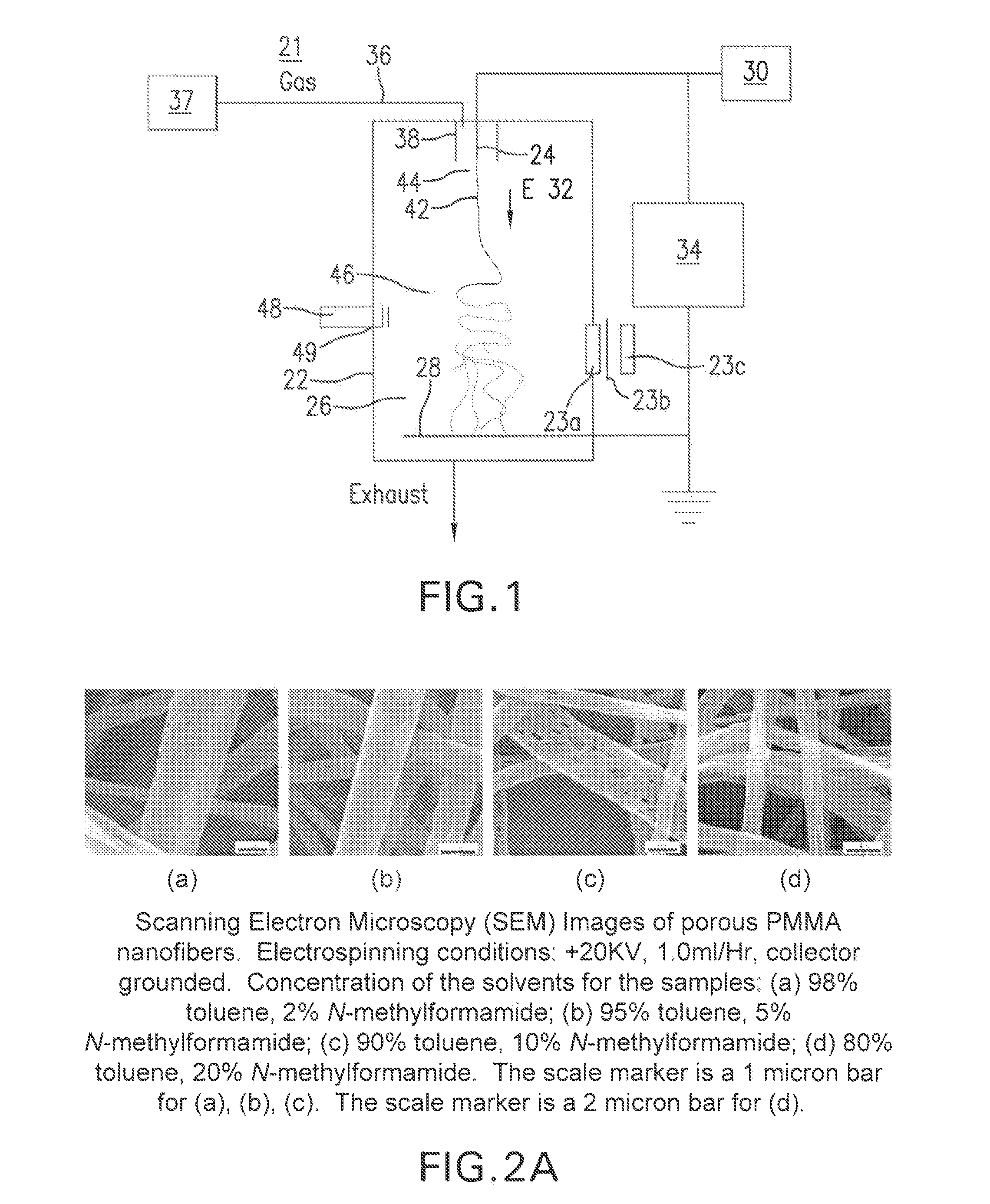
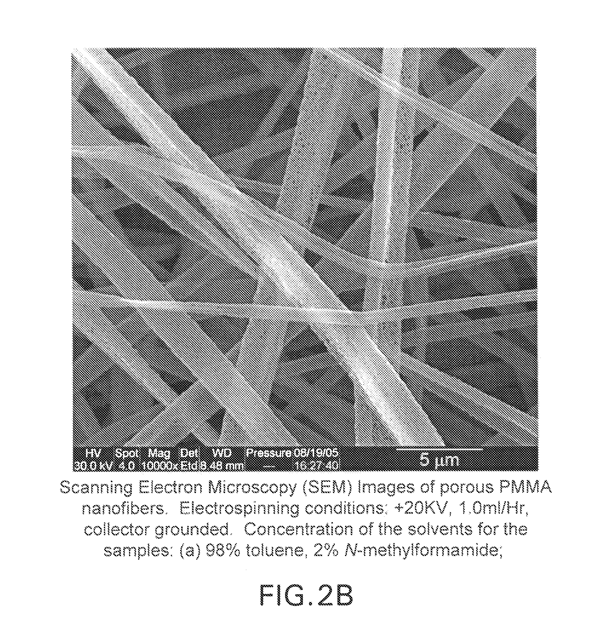
[0036]Nanofibers typically have a solid structure that can have one dimension (e.g., their diameter) in the 10-2000 nm range, while the other dimensions (e.g., the length) can be quite long such as for example even meters in dimension. Nanofibers suitable for the invention can be made from a variety of materials, including polymers, ceramics, and glasses, sol gels, polyimides, and blends of materials can also be readily fabricated.

[0037]One feature of nanofibers is their small diameter and consequently high surface area. Nanofiber diameters on the order of visible light (˜500 nm) or even smaller can be readily produced using the methods disclosed herein creating very large surface areas. A surface of the polymer nanofibers can be smooth or rough, such as porous feature. A rough surface morphology of the nanofiber normally presents an even larger surface area of the nanofiber material than would be available if the nanofiber material were smooth. In one example of a porous surface fe...


PUM

PropertyMeasurementUnit
Fractionaaaaaaaaaa
Fractionaaaaaaaaaa
Thicknessaaaaaaaaaa

Abstract

A method for producing a fiber membrane of nanofibers that have both smooth and porous surface features. The method includes materials processing using polymer mixes with solvents and melt polymers with additives. The method includes nanomaterial incorporation onto a fiber structure after formation of the fiber structure. The fiber structure can be a part of a nanoparticle carrier material, a nanoparticle disposal medium, a lighting medium, and a catalysis medium.

Description

CROSS REFERENCE TO RELATED APPLICATIONS[0001]This application is related to U.S. application Ser. No. 10 / 819,916, filed on Apr. 8, 2004, entitled “Electrospinning of Polymer Nanofibers Using a Rotating Spray Head,” Attorney Docket No. 241015US-2025-2025-20, the entire contents of which are incorporated herein by reference. This application is also related to U.S. application Ser. No. 10 / 819,942, filed on Apr. 8, 2004, entitled “Electrospray / electrospinning Apparatus and Method,” Attorney Docket No. 241013US-2025-2025-20, the entire contents of which are incorporated herein by reference. This application is related to U.S. application Ser. No. 10 / 819,945, filed Apr. 8, 2004, entitled “Electrospinning in a Controlled Gaseous Environment,” Attorney Docket No. 245016US-2025-2025-20, the entire contents of which are incorporated herein by reference. This application is related to U.S. Ser. No. 11 / 130,269, filed May 17, 2005 entitled “Nanofiber Mats and Production Methods Thereof,” Attorn...

Claims


Application Information

Patent Timeline
IPC IPC(8): H01L33/20B29C47/00B32B5/16B32B5/02B32B1/06B05D1/24B05D3/02B05D1/36B01D39/00B01D37/00B65G35/00B01J35/02B82Y20/00B82Y30/00B82Y40/00D04H1/728
CPCY10T428/239D01D5/003D06M11/68D06M10/02B01D2239/0258D06M11/53B01D2239/025D04H3/16D06M11/52D06M11/44D06M11/51D06M23/08D01D5/247D01D5/0023D06M11/46D06M11/42D04H3/02Y10T428/249921Y10T428/249962
Inventor HAN, LIANDRADY, ANTHONY L.DAVIS, JAMES LYNN
Owner RES TRIANGLE INST
Learn More