Driving circuit and apparatus, and image forming apparatus
- Summary
- Abstract
- Description
- Claims
- Application Information
AI Technical Summary
Benefits of technology
Problems solved by technology
Method used
Image
Examples
first embodiment
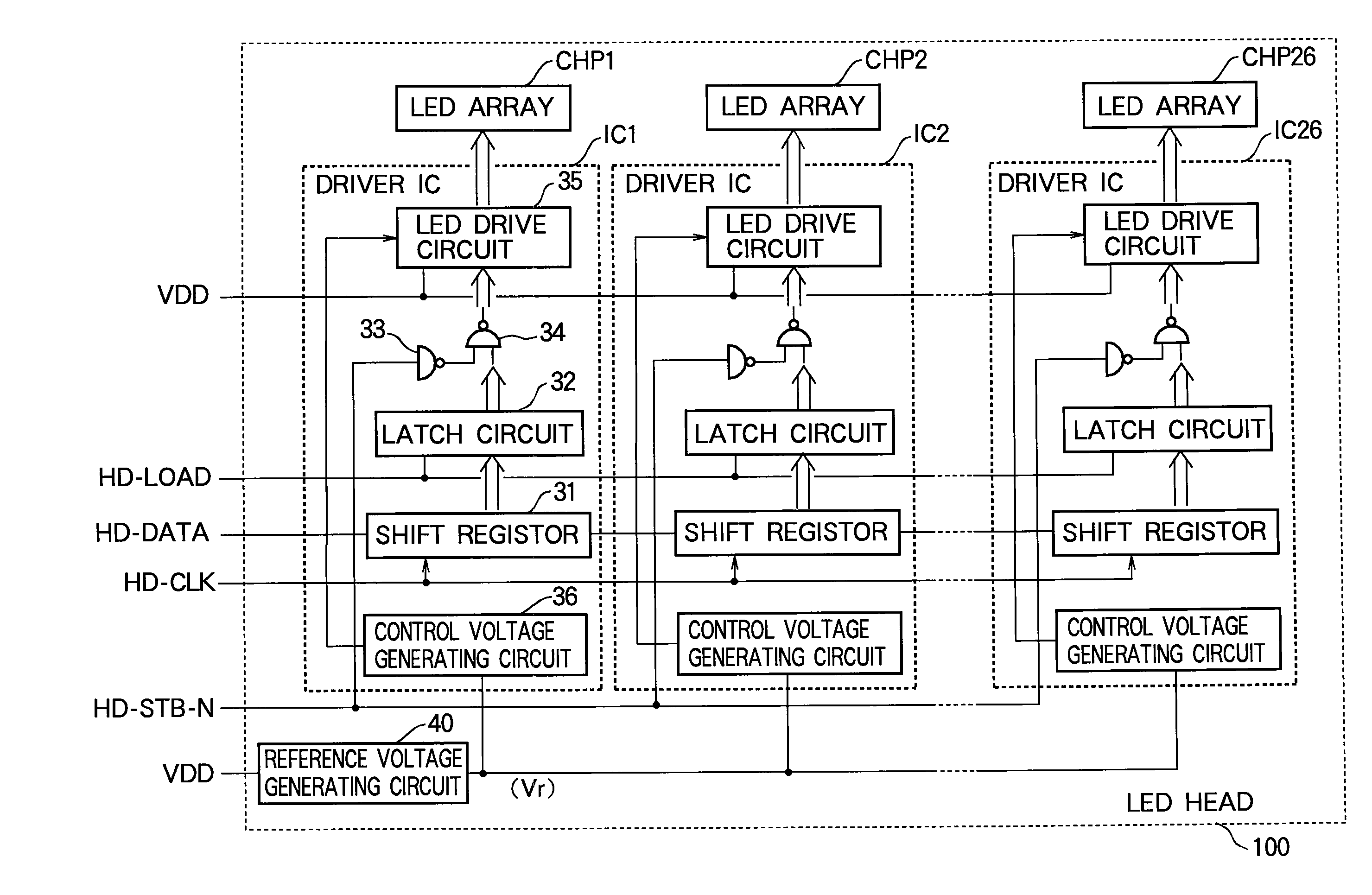
[0038]In an electrophotographic printer (an LED printer, for example), an optical print head (an LED head, for example) selectively illuminates the surface of a photosensitive drum according to print information to form a latent electrostatic image on the drum surface. The latent image is developed by application of toner to form a toner image, which is then transferred from the drum surface to paper and fixed onto the paper by heat and pressure.
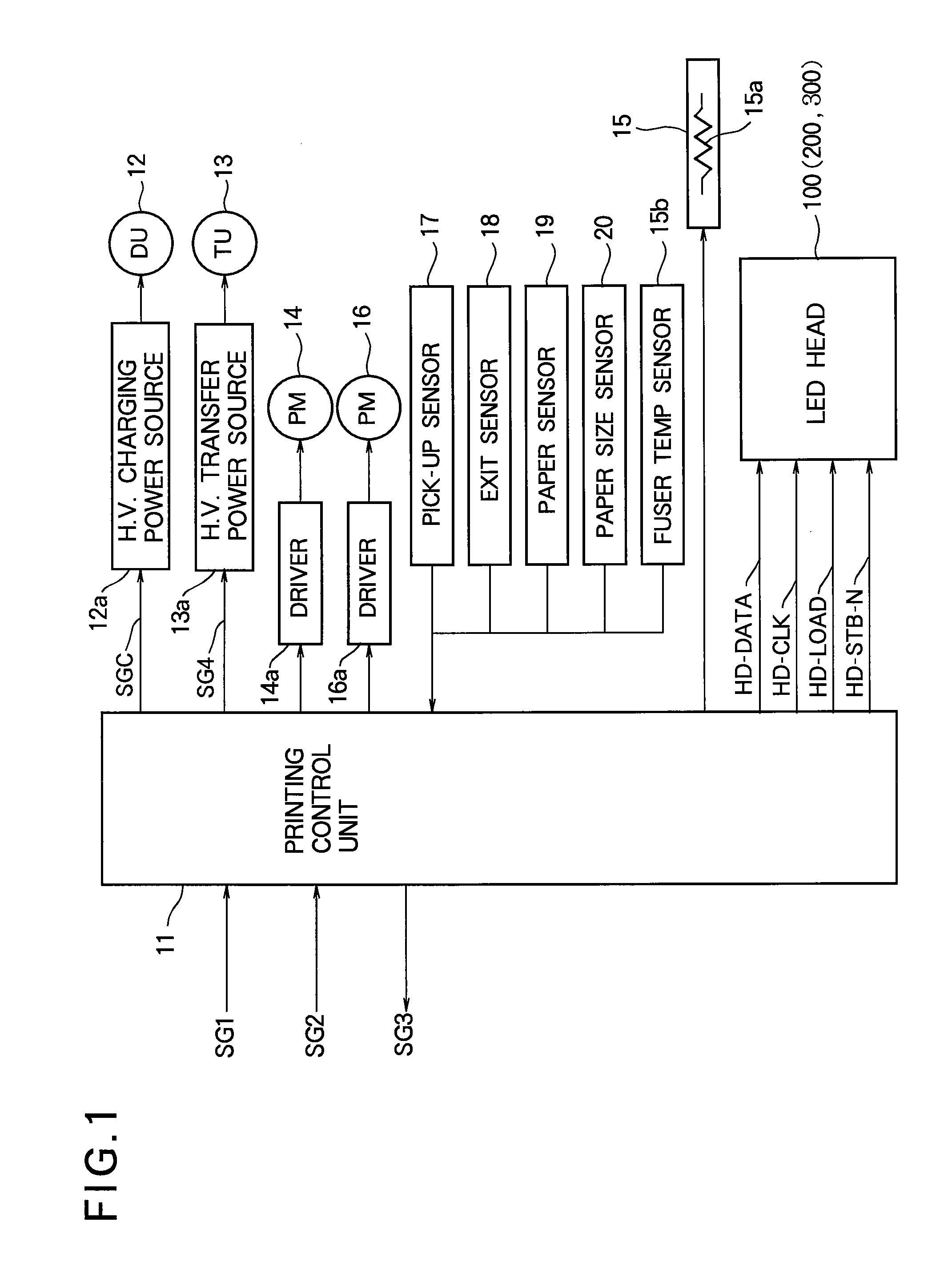
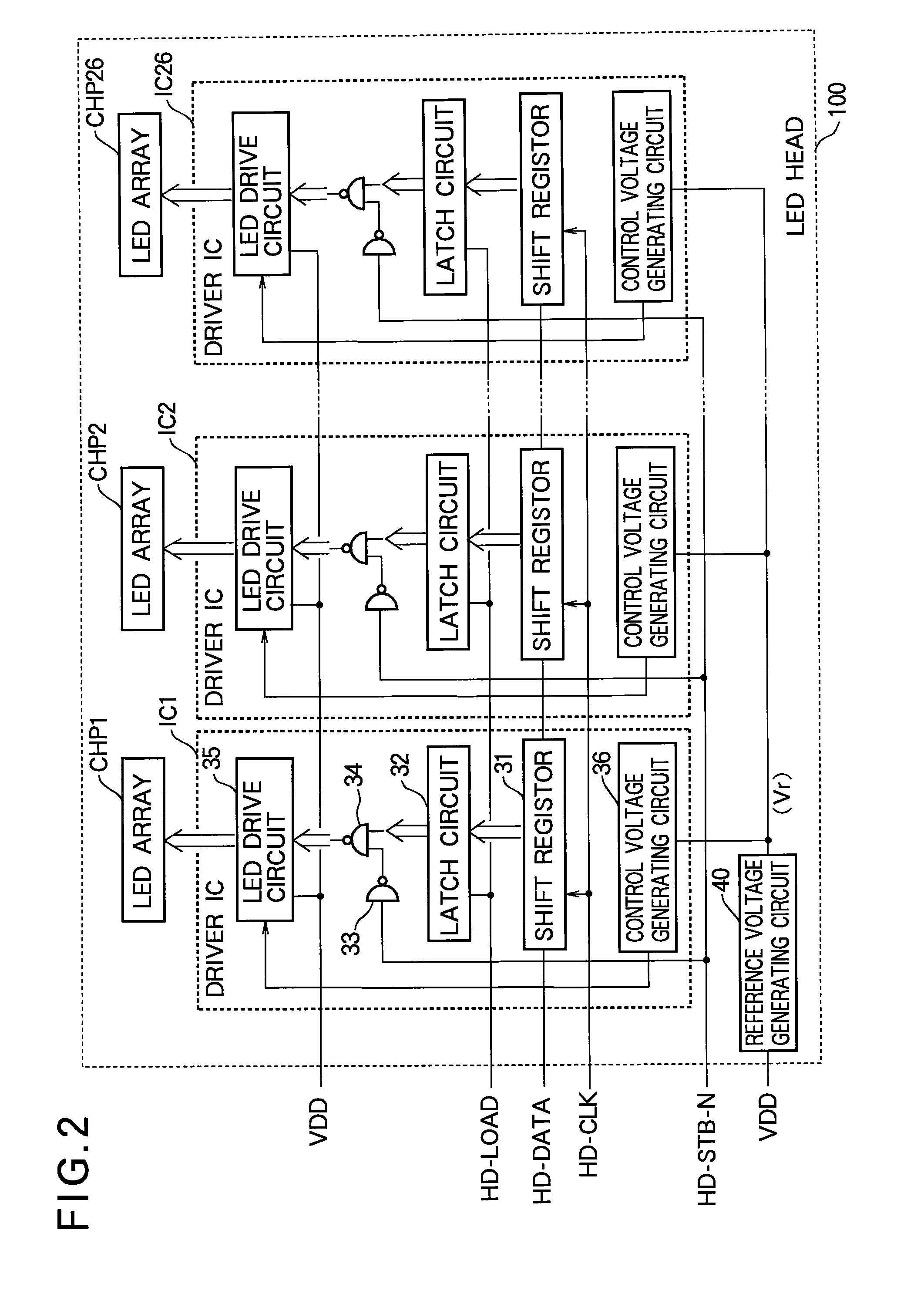
[0039]Referring to FIG. 1, an LED printer according to the first embodiment includes a printing control unit 11, a developing unit (DU) 12, a high-voltage (H.V.) charging power source 12a that applies a voltage to the developing unit 12, a transfer unit (TU) 13, a high-voltage transfer power source 13a that applies a voltage to the transfer unit 13, a develop / transfer process motor (PM) 14, a motor driver 14a that drives the develop / transfer process motor 14, a fuser 15 with an internal heater 15a, a fuser temperature (Temp.) sensor 15b, a p...
example 5
[0078]If V1 is 0.8 V (V1=0.8 V), the temperature coefficient Tc is:
Tc=1 / (0.8V-0.6V)×2mV / °C.=+1.0% / °C.
[0079]If R2 / R1 is five (R2 / R1=5), the reference voltage Vr at the VREF terminal is:
Vr=(1+R2 / R1)×(V1-Vbe)=(1+5)×(0.8V-0.6V)=1.2V
[0080]Whereas the reference voltage Vra is only 0.2 V in the corresponding comparative example (4) for the conventional reference voltage generating circuit 90 in FIG. 5, the reference voltage Vr in the reference voltage generating circuit 40 in FIG. 3 in the first embodiment can provide a reference voltage of 1.2 V, which is large enough to reduce noise voltage effects to a negligible level.
[0081]The presence of the operational amplifier 46 in the voltage amplifying section 53 adds to the cost of the reference voltage generating circuit 40 in the first embodiment. Even if reference voltage generating circuit 40 is manufactured as a monolithic integrated circuit chip, the operational amplifier 46 occupies relatively large chip area, increasing the chip cost. ...
second embodiment
[0085]Referring to FIG. 6, the LED head 200 in the second embodiment has the same configuration as the LED head 100 in the first embodiment but differs in the internal configuration of the reference voltage generating circuit. Three exemplary reference voltage generating circuits 70a, 70b, 70c will be shown.
[0086]Referring to FIG. 7, reference voltage generating circuit 70a includes the regulator circuit 41, npn bipolar transistor 42, and resistor 43 described in the first embodiment, a pair of p-channel metal-oxide-semiconductor field effect transistors (PMOS transistors) 81, 82, and a resistor 83. As in the first embodiment, the regulator circuit 41 has a power terminal 41a connected to the power source VDD, a ground terminal 41c connected to ground, and an output terminal 41b connected to the base terminal 42b of the npn bipolar transistor 42. The npn bipolar transistor 42 has its emitter terminal 42e connected to ground through resistor 43, the npn bipolar transistor 42 and resi...
PUM
 Abstract
Description
Claims
Application Information
 - R&D
- Intellectual Property
- Life Sciences
- Materials
- Tech Scout
- Unparalleled Data Quality
- Higher Quality Content
- 60% Fewer Hallucinations
Browse by: Latest US Patents, China's latest patents, Technical Efficacy Thesaurus, Application Domain, Technology Topic, Popular Technical Reports.
© 2025 PatSnap. All rights reserved.Legal|Privacy policy|Modern Slavery Act Transparency Statement|Sitemap|About US| Contact US: help@patsnap.com


