Liquid ejecting apparatus, and nozzle recovery method used in liquid ejecting apparatus

Active Publication Date: 2011-08-11
SEIKO EPSON CORP
View PDF4 Cites 6 Cited by
  • Summary
  • Abstract
  • Description
  • Claims
  • Application Information

AI Technical Summary

Benefits of technology

[0009]In this configuration, when the pump is driven to perform the sucking operation, the liquid in the liquid supply passage is sucked. Then, the bubbles incorporated into the liquid in the liquid ejecting head are moved into the liquid supply passage along with the liquid and thus the liquid is clarified by the liquid filtration unit. Accordingly, thereafter, when the liquid is discharged to the liquid supply passage as the pump is driven to perform the discharging operation, the clarified liquid is moved to the nozzle side as a result of receiving the discharge pressure. Moreover, as the capillary force of the nozzles is exerted, the nozzles are filled with the clarified liquid, thereby completing the recovery process of the nozzles. As such, during the recovery process of the nozzles, the bubbles incorporated into the liquid can be removed without discharging the liquid out of the nozzle opening. Therefore, the recovery process of the nozzles can be performed while suppressing liquid consumption.
[0011]In this configuration, the liquid in the liquid supply passage can be caused to flow by the circulation passage and the circulation unit. Accordingly, for example, even in the case where the liquid evaporates and the viscosity of the liquid increases, the sucked liquid and liquid which is supplied from the upstream side and has low viscosity are mixed with each other, thereby reducing the viscosity of the ink. Therefore, the viscosity of the thickened liquid can be reduced and the liquid can be re-filled in the nozzles, thereby performing the recovery process of the nozzles while suppressing liquid consumption.
[0013]In this configuration, as the filter is provided in the circulation passage, the liquid which is acquired from the liquid supply passage and caused to flow through the circulation passage passes through the filter and is caused to flow out to the liquid supply passage. Therefore, bubbles in the liquid or foreign matter incorporated into the liquid can be easily removed.

Problems solved by technology

In one of these printers, when bubbles are incorporated into the ink in the recording head, the ink cannot be properly ejected from the nozzles, resulting in degradation in printing quality.
As a result, the ink is wastefully discharged from the nozzles in normal condition, and a large amount of ink is wasted due to the nozzle recovery process.

Method used


Image

  • Liquid ejecting apparatus, and nozzle recovery method used in liquid ejecting apparatus
  • Liquid ejecting apparatus, and nozzle recovery method used in liquid ejecting apparatus
  • Liquid ejecting apparatus, and nozzle recovery method used in liquid ejecting apparatus

Examples


Embodiment Construction

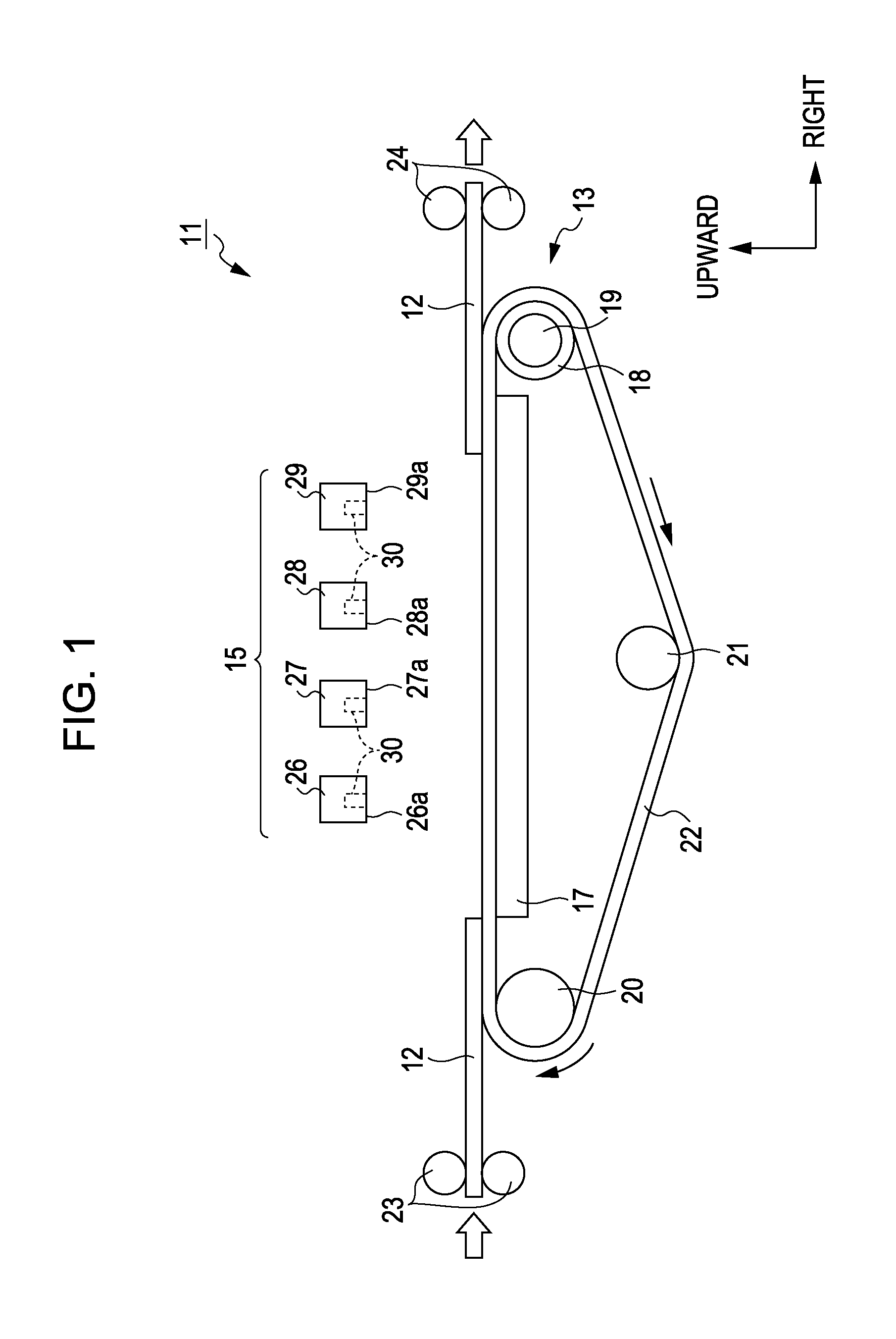
[0023]Hereinafter, a fluid ejecting apparatus embodied as an ink jet printer according to exemplary embodiments of the invention will be described with reference to the accompanying drawings. Moreover, in the following description, a “left and right direction” and an “up and down direction” respectively represent a left and right direction and an up and down direction indicated by arrows in FIG. 1. In addition, a “front and rear” direction represents a direction perpendicular to the paper plane of FIG. 1.

[0024]As illustrated in FIG. 1, an ink jet printer (hereinafter, also called a “printer”) 11 as a liquid ejecting apparatus includes a transportation unit 13 for transporting a sheet 12 as a target, and a recording head unit 15 for performing printing on the sheet 12.

[0025]The transportation unit 13 includes a platen 17 which has a long rectangular plate shape in the left and right direction. A driving roller 18 extending in the front and rear direction is disposed on the right of t...


PUM


Abstract

A liquid ejecting apparatus includes a recording head that ejects an ink from a plurality of nozzles, a liquid supply passage and a reservoir that supply the ink from an upstream side toward a downstream side, a maintenance pump that is able to suck and discharge the ink from and to the liquid supply passage, a filter that clarify the ink in the reservoir, and a control unit that performs a recovery process of the nozzles by controlling an operation of the pump, wherein the control unit causes the maintenance pump to perform a sucking operation to suck the ink, and then causes the pump to perform a discharging operation to discharge the ink, thereby supplying the ink clarified by the filter to the nozzle side.

Description

BACKGROUND[0001]1. Technical Field[0002]The present invention relates to a liquid ejecting apparatus such as an ink jet printer and a nozzle recovery method used in a liquid ejecting apparatus.[0003]2. Related Art[0004]Ink jet printers have been widely known as liquid ejecting apparatuses for ejecting liquid to a target. These printers perform printing (image formation) on the target by ejecting ink (liquid) supplied to a recording head (liquid ejecting head) from nozzles provided in the recording head.[0005]In one of these printers, when bubbles are incorporated into the ink in the recording head, the ink cannot be properly ejected from the nozzles, resulting in degradation in printing quality. Accordingly, in such a printer, for example, as disclosed in JP-A-2007-152725, a nozzle recovery process is performed by pressurizing the ink, which is supplied from an ink cartridge to the recording head, and thereby pushing the ink containing the bubbles out of the recording head through n...

Claims


Application Information

Patent Timeline
IPC IPC(8): B41J2/175
CPCB41J2/175B41J2/17596B41J2/17563
Inventor ARUGA, TOMOHIROKOBASHI, MASARU
Owner SEIKO EPSON CORP
Why Eureka
Try Eureka