Fuel filter
a technology of fuel filter and filter body, which is applied in the direction of filtration separation, machine/engine, separation process, etc., can solve the problems of increasing the cost and increasing the complexity of the work for securing the fuel filter to the sub-tank by the fixture members, etc., to achieve the effect of reducing the number of parts of the fuel-feeding device having the fuel filter, easy and inexpensive manufacturing
- Summary
- Abstract
- Description
- Claims
- Application Information
AI Technical Summary
Benefits of technology
Problems solved by technology
Method used
Image
Examples
first embodiment
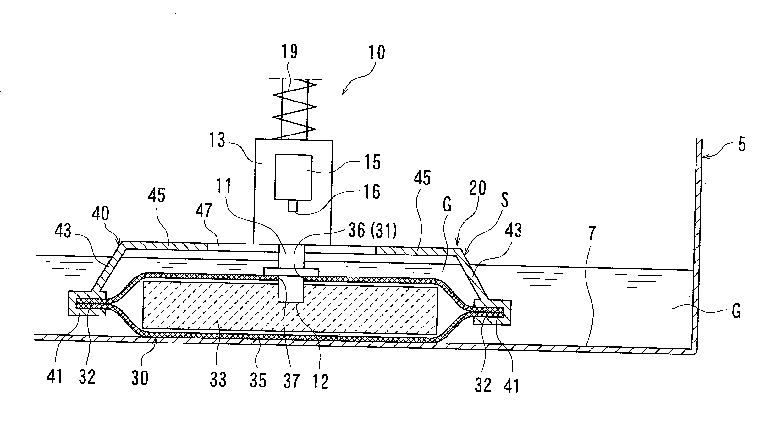
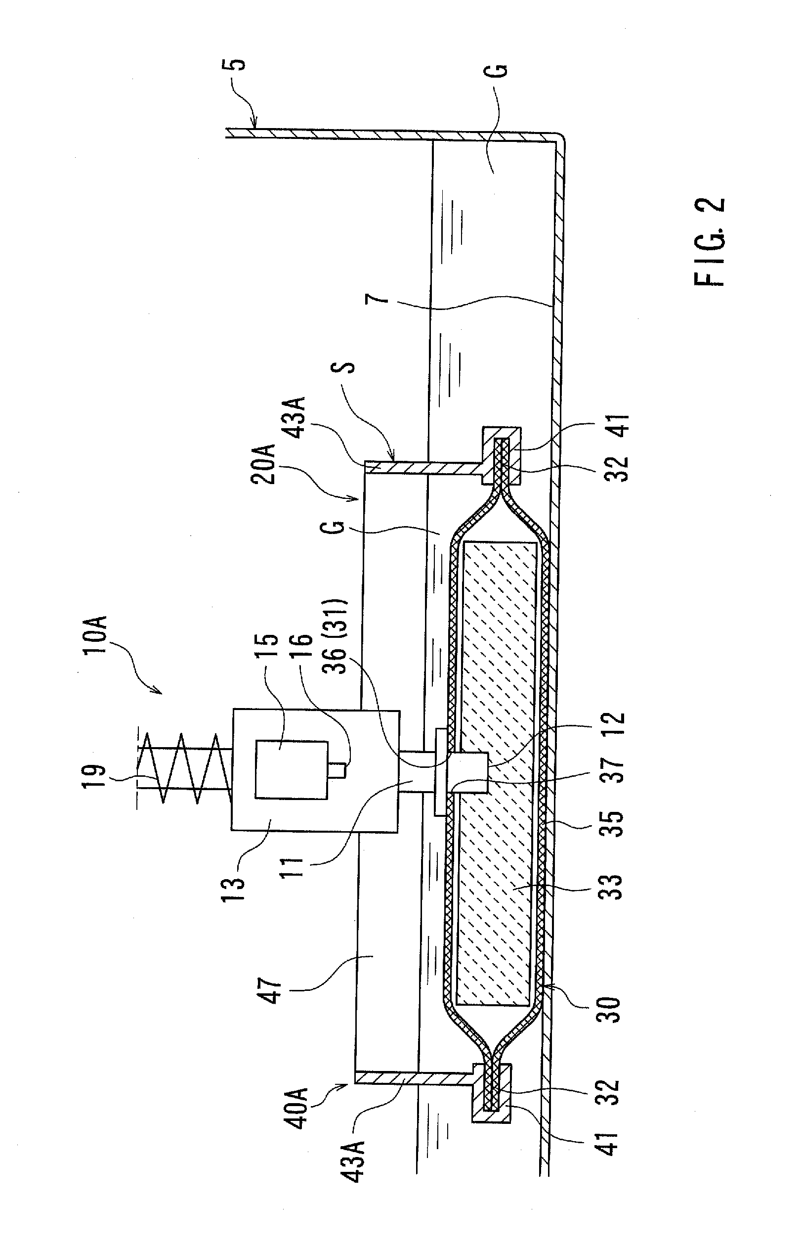
[0032]A first embodiment of the present invention will be described with reference to FIGS. 1 to 4. This embodiment of the present invention is directed to a fuel filter that is used in a fuel-feeding device of an engine (an internal combustion engine) of a vehicle such as a four-wheeled vehicle.
[0033]First, a fuel-feeding device 10 is described. As shown in FIG. 1, the fuel-feeding device 10 may preferably be disposed in a hollow fuel tank 5 of a vehicle (not shown) in which liquid fuel or gasoline G is received. The fuel-feeding device 10 may preferably include a suction pipe 11 (a gasoline flow conduit), a fuel filter 20, an immersion type fuel pump 13 that is capable of feeding (pumping) the gasoline G received in the fuel tank 5 to an engine (not shown), and a pressure regulator 15 that is connected to the fuel pump 13. The suction pipe 11, the fuel filter 20, the fuel pump 13, and the pressure regulator 15 are integrated with each other. Further, the fuel filter 20 is construc...
second embodiment
[0057]The second detailed representative embodiment will now described with reference to FIG. 5.
[0058]Because the second embodiment relates to the first embodiment, only the constructions and elements that are different from the first embodiment will be explained in detail. Elements that are the same in the first and second embodiments will be identified by the same reference numerals and a detailed description of such elements may be omitted.
[0059]As shown in FIG. 5, in a fuel filter 20B of this embodiment, the wall member 40 (40A) of the first embodiment is replaced with a wall member 60. The wall member 60 has a connecting portion 61 formed in the side wall portion 43 thereof. Unlike the connecting portion 41 of the first embodiment, the connecting portion 61 is constructed of two portions that are vertically separated from each other so as to hold or clamp the circumferential periphery 32 of the filter member 30 therebetween. In particular, the connecting portion 61 includes a f...
third embodiment
[0062]The third detailed representative embodiment will now described with reference to FIGS. 6(A) to 6(C).
[0063]Because the third embodiment relates to the second embodiment, only the constructions and elements that are different from the second embodiment will be explained in detail. Elements that are the same in the second and third embodiments will be identified by the same reference numerals and a detailed description of such elements may be omitted.
[0064]As shown in FIG. 6(A), in a fuel filter 20C of this embodiment, the filter member 30 of the second embodiment is replaced with a filter member 50. Unlike the filter member 30, the filter member 50 has a reinforcement member 55 that is embedded in the non-woven fabric filter element 33. The reinforcement member 55 has ribs 56 in order to effectively reinforcing or rigidifying the filter member 50. Further, the reinforcement member 55 may preferably be made of nylon resin similar to the nylon resin of the mesh filter element 35....
PUM
| Property | Measurement | Unit |
|---|---|---|
| Melting point | aaaaa | aaaaa |
Abstract
Description
Claims
Application Information
 - R&D
- Intellectual Property
- Life Sciences
- Materials
- Tech Scout
- Unparalleled Data Quality
- Higher Quality Content
- 60% Fewer Hallucinations
Browse by: Latest US Patents, China's latest patents, Technical Efficacy Thesaurus, Application Domain, Technology Topic, Popular Technical Reports.
© 2025 PatSnap. All rights reserved.Legal|Privacy policy|Modern Slavery Act Transparency Statement|Sitemap|About US| Contact US: help@patsnap.com


