Optical pickup
a pickup and optical technology, applied in the field of optical pickups, can solve problems such as mismatching between, and achieve the effect of stable tracking control
- Summary
- Abstract
- Description
- Claims
- Application Information
AI Technical Summary
Benefits of technology
Problems solved by technology
Method used
Image

Examples
first embodiment
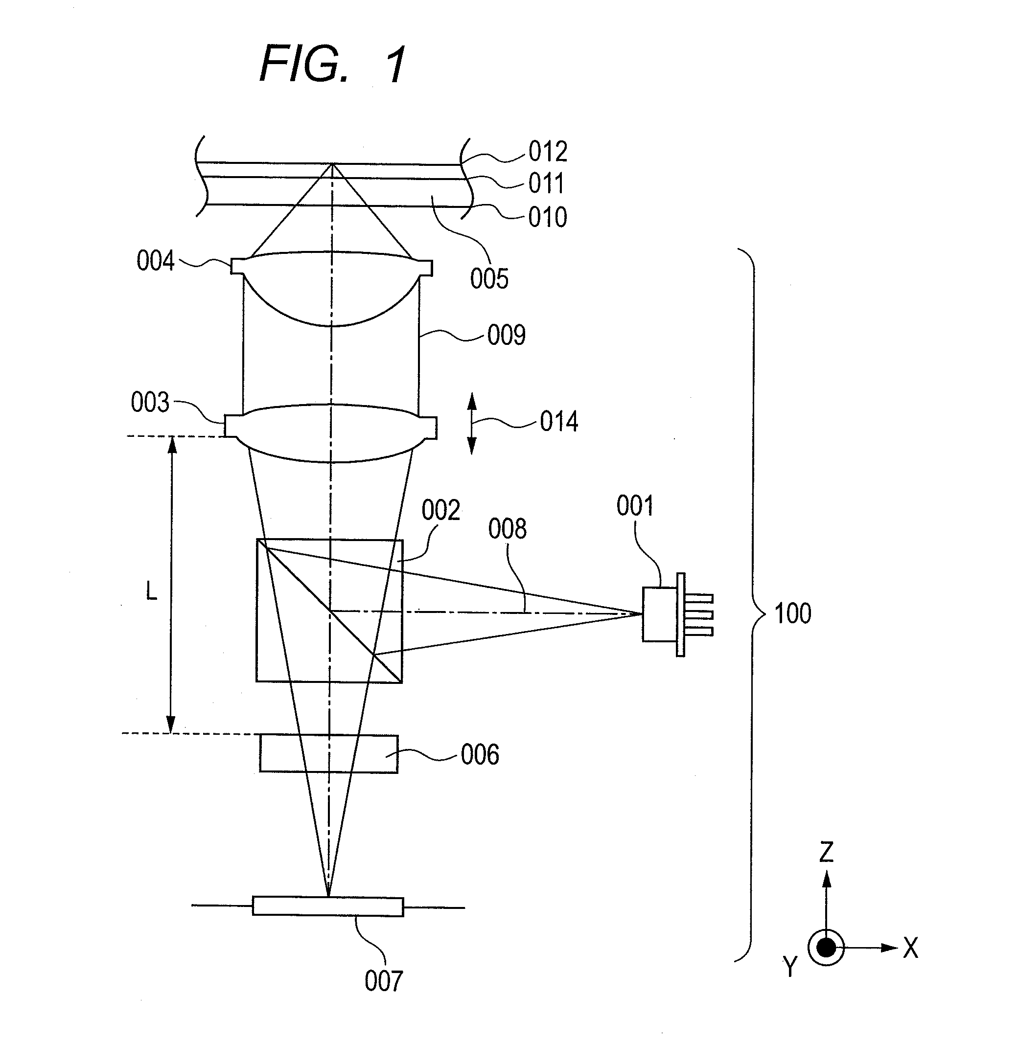
[0029]An optical pickup according to a first embodiment of the present invention is described in detail below. An optical pickup adapted for recording information on or reproducing information from a double-layered disc of current Blu-ray disc (BD) standards is described first. FIG. 1 is a schematic diagram showing a configuration of the optical pickup 100 according to the first embodiment. In the figure, the X-direction is equivalent to the radial direction of the optical disc, the Z-direction to the vertical direction thereof, and the Y-direction to the direction parallel to tracks of the optical disc.
[0030]An optical beam is emitted as divergent light from a light source 001. Recording information on or reproducing information from a BD generally uses a semiconductor laser that emits optical beams of 405±10 nm in wavelength. The present embodiment assumes that the light source 001 emits optical beams of 405±10 nm in wavelength. A dotted-and-dashed line 008 denotes a central optic...
second embodiment
[0115]A modification in the optical pickup of the first embodiment is described below as a second embodiment. The optical pickup of the second embodiment, a modification in the optical pickup 100 of the first embodiment, differs from the optical pickup 100 of the first embodiment in terms of region layout in a diffraction grating and photo-receiver layout in a detector. The present embodiment, as with the first embodiment, envisages information reproduction from a double-layered disc having a 25-μm space between two information layers.
[0116]FIG. 8 shows the diffraction grating 015 of the second embodiment, as viewed from the detector side. The diffraction grating 015 includes a region AB, which is equivalent to a region formed by combining the regions A and B of the diffraction grating 006. The diffraction grating 015 also includes a region CD, which is equivalent to a region likewise formed by combining the regions C and D of the diffraction grating 006. The regions AB and CD of th...
third embodiment
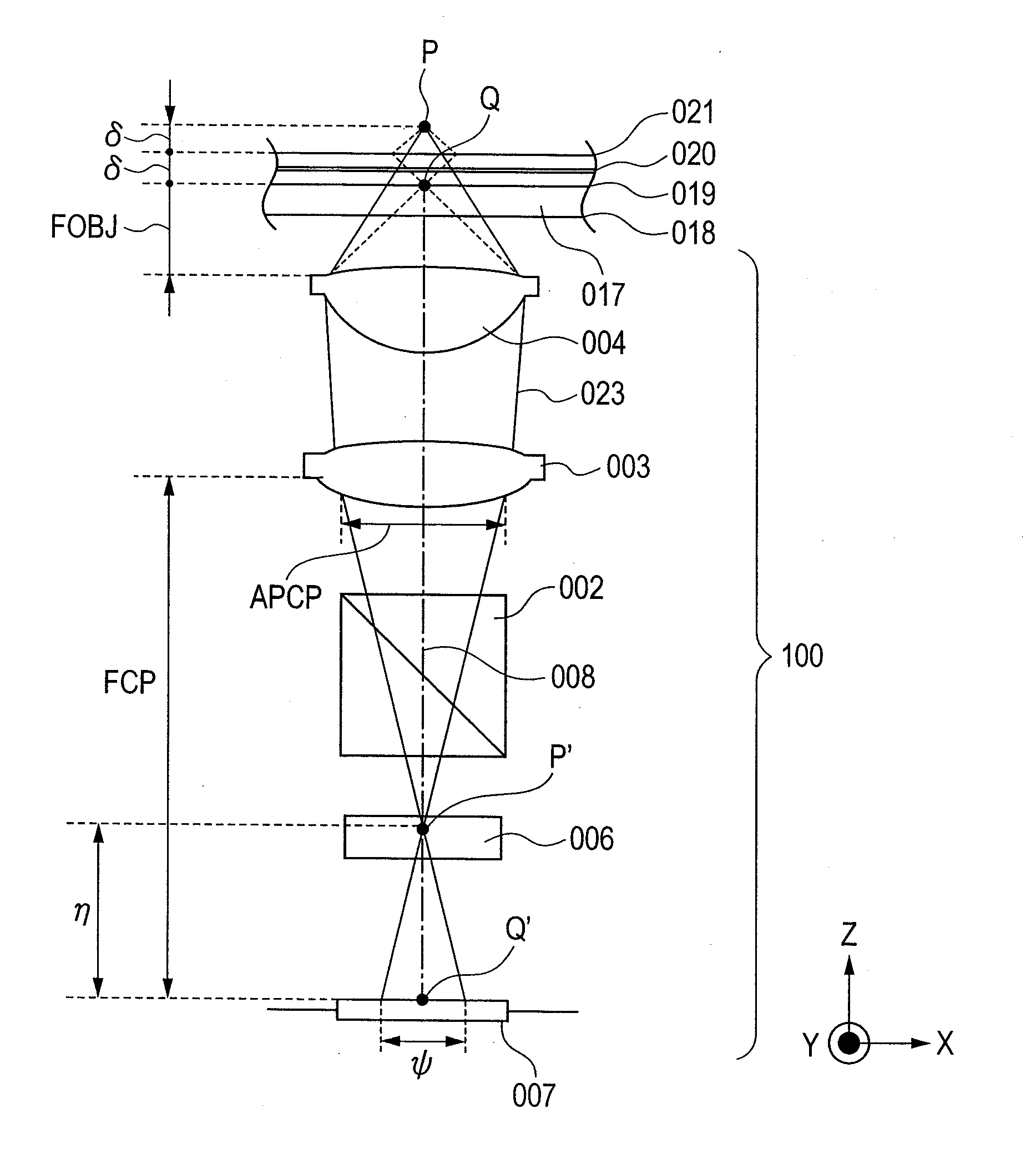
[0141]Using the optical pickup of the first embodiment to reproduce information from a triple-layered optical disc having three information layers is described as a third embodiment. Standards specify that double-layered discs should have a 25-μm space between the two information layers. The present embodiment envisages a triple-layered disc formed by adding a third information layer to a surface side of a double-layered disc, with the same space of 25 μm as that of double-layered discs,
[0142]In the present embodiment, the triple-layered disc is denoted as 017, an information layer located nearest to the surface of the triple-layered disc, as 019, an intermediate information layer as 020, and an information layer located farthest from the surface, as 021. Interlayer tolerances for the three information layers are ±5 μm, the same tolerances as defined in double-layered disc standards. The space between the information layer 019 nearest the surface, and the information layer 021 farth...
PUM
| Property | Measurement | Unit |
|---|---|---|
| distance | aaaaa | aaaaa |
| center-to-center distance | aaaaa | aaaaa |
| wavelength | aaaaa | aaaaa |
Abstract
Description
Claims
Application Information
 - R&D
- Intellectual Property
- Life Sciences
- Materials
- Tech Scout
- Unparalleled Data Quality
- Higher Quality Content
- 60% Fewer Hallucinations
Browse by: Latest US Patents, China's latest patents, Technical Efficacy Thesaurus, Application Domain, Technology Topic, Popular Technical Reports.
© 2025 PatSnap. All rights reserved.Legal|Privacy policy|Modern Slavery Act Transparency Statement|Sitemap|About US| Contact US: help@patsnap.com