Opitical disc device and tracking and slider control method

a technology of optical discs and sliders, applied in the direction of digital signal error detection/correction, instruments, recording signal processing, etc., can solve the problems of heavy load on the controller in charge of tracking control, inability to perform tracking control, tracking servo instable, etc., and achieve the effect of stable tracking control

Active Publication Date: 2008-12-11
HITACHI-LG DATA STORAGE +1
View PDF4 Cites 3 Cited by
  • Summary
  • Abstract
  • Description
  • Claims
  • Application Information

AI Technical Summary

Benefits of technology

[0014]According to this invention, the objective lens can be moved to the center position of a track displacement range being tracked by the track pull-in. Therefore, moving the objective lens so as to follow the track can be performed within the movable range of the objective lens. As a result, it is possible to perform stable tracking control also for an inferior optical disc with tracks decentered by a large amount.

Problems solved by technology

The conventional tracking control method described above has a problem, i.e., information for moving the neutral position of the objective lens to the center position of the track displaced due to the eccentricity of the optical disc can be obtained only after one or more revolutions of the optical disc after track pull-in.
However, in the case of an inferior optical disc whose eccentricity amount exceeds the movable range of the objective lens, moving of the objective lens cannot follow runout of the optical disc attributable to the eccentricity of the optical disc and, therefore, the tracking control cannot be performed.
However, if the above-described method is used for high-speed recording / reproduction of an optical disc or for recording / reproduction of a high-density disc such as a Blu-ray Disc (BD), controlling the slider to have it follow the track displaced due to the eccentricity of the optical disc, and concurrently performing tracking control by activating a tracking actuator require cumbersome control processing, resulting in a problem of making the tracking servo instable and a heavy load on a controller in charge of the tracking control.

Method used


Image

  • Opitical disc device and tracking and slider control method
  • Opitical disc device and tracking and slider control method
  • Opitical disc device and tracking and slider control method

Examples


first embodiment

(1-3) Effect of First Embodiment

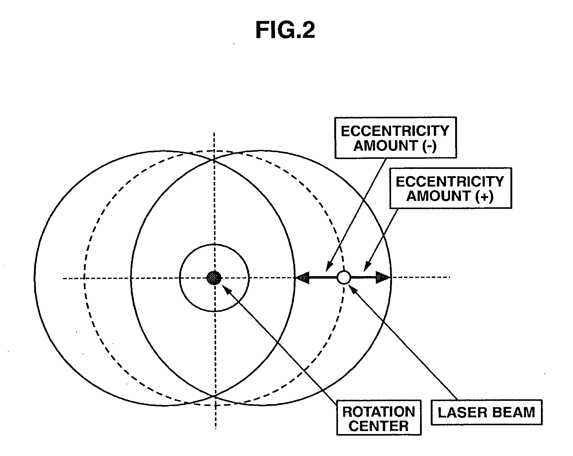
[0086]The optical disc device 1 according to the first embodiment as described above obtains the rotation angle of the optical disc 4 at which the degree of displacement of the track due to the optical disc 4 track decentering becomes maximum on the inner circumference and the outer circumference; finds the eccentricity amount of the optical disc 4; performs track pull-in at the rotation angle of the optical disc 4 at which the degree of displacement of the track due to the optical disc 4 track decentering becomes maximum; detects a displacement direction of the optical disc 4 at the time of this track pull-in; and activates the slider mechanism 12 to move the optical pickup 10 in that displacement direction for a distance equal to or almost equal to the eccentricity amount of the optical disc 4. As a result, the objective lens 11 can be moved to the center position or approximately the center position of the track displacement range being tracked by ...

second embodiment

(2) Second Embodiment

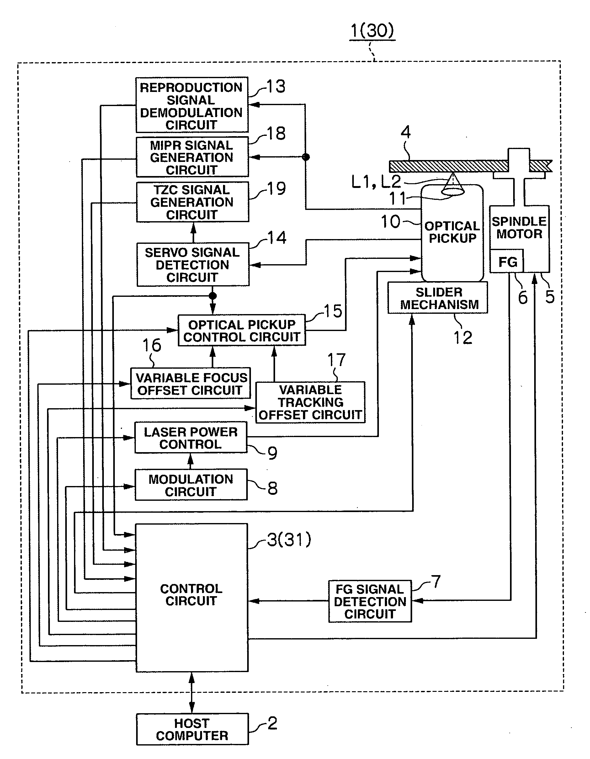
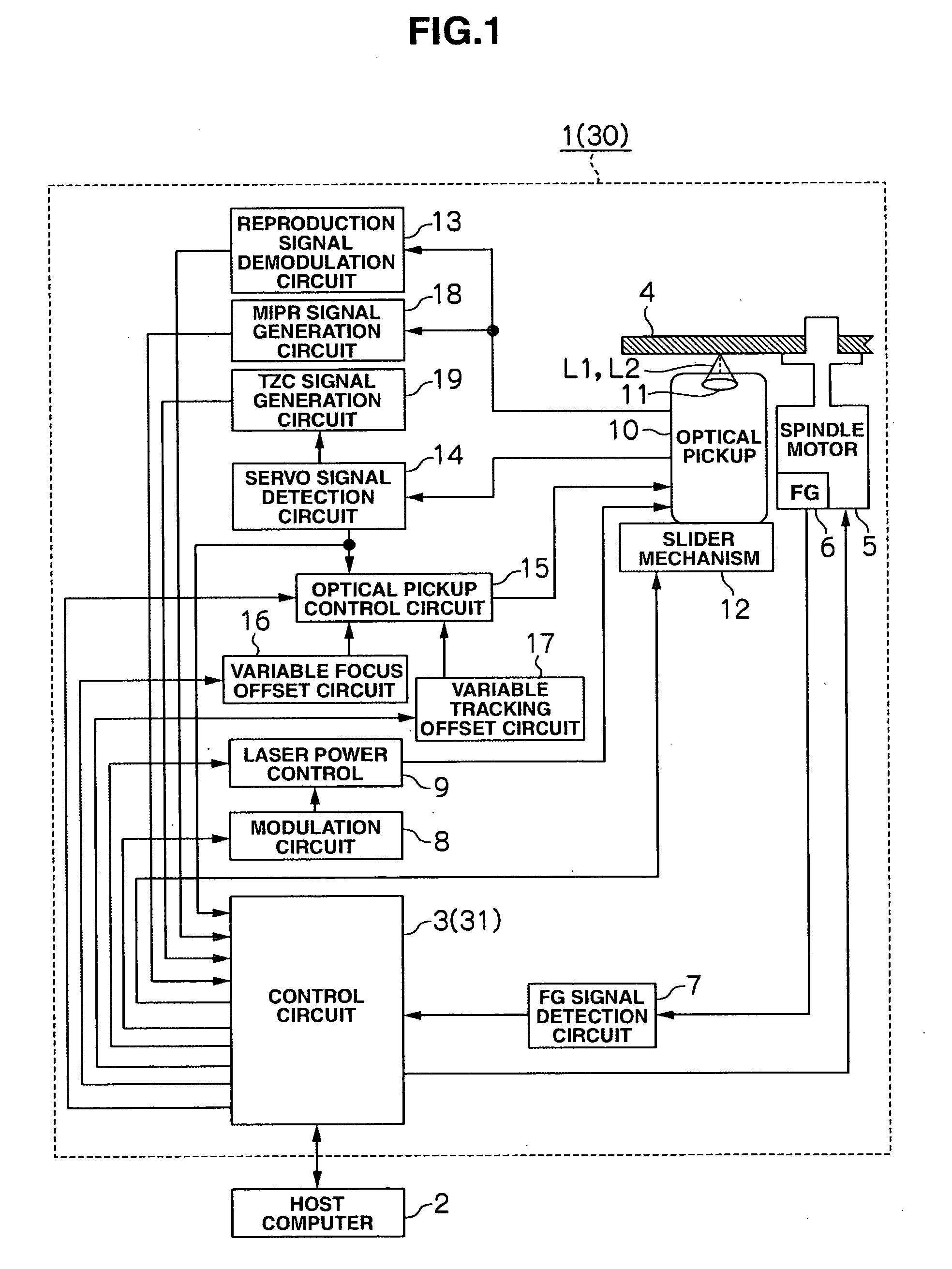
[0089]Referring to FIG. 1, reference numeral “30” represents an optical disc device according to the second embodiment. This optical disc device 30 is configured in the same manner as the optical disc device 1 according to the first embodiment, except there is some difference in the details of disc rotation angle obtaining processing and slider movement processing executed by a control circuit 31.

[0090]Specifically speaking, the optical disc device 1 according to the first embodiment obtains the rotation angle, at which the degree of displacement of the track due to the optical disc 4 track decentering becomes maximum on the inner circumference side and the outer circumference side, by finding when the logical level for the track-crossing-direction detecting signal (FIG. 7(C)) changes. However, as shown in FIG. 11(A), the waveform of the tracking error signal may become unstable before and after the logical level for the track-crossing-direction detecting signal...


PUM

PropertyMeasurementUnit
timeaaaaaaaaaa
rotation angleaaaaaaaaaa
angleaaaaaaaaaa

Abstract

An optical disc device and tracking control method capable of stable tracking control even for inferior optical discs with tracks decentered by a large amount. The optical disc device and tracking control method includes: obtaining a rotation angle at which the degree of displacement of the track due to the eccentricity of the optical disc becomes maximum on the inner circumference side and the outer circumference side, and detecting the eccentricity amount of the optical disc; and performing track pull-in at the rotation angle, at which the degree of displacement of the track due to the eccentricity of the optical disc becomes maximum, detecting a displacement direction of the optical disc at the time of the pull-in, and moving the slider in the detected displacement direction for a distance equal to or almost equal to the eccentricity amount of the optical disc.

Description

CROSS-REFERENCE TO RELATED APPLICATION(S)[0001]This application relates to and claims priority from Japanese Patent Application No. 2007-145512, filed on May 31, 2007, the entire disclosure of which is incorporated herein by reference.BACKGROUND OF THE INVENTION[0002]The invention relates to an optical disc device and a tracking and slider control method and is ideal for use in, for example, an optical disc device capable of high-speed recording / reproduction and high-density recording / reproduction.DESCRIPTION OF RELATED ART[0003]Conventionally, tracking control for an eccentricity of an optical discs is performed as outlined below.[0004]First, track-crossing frequency due to an eccentricity of an optical disc is detected when the tracking servo is turned off; and then the tracking servo is turned on, i.e., track pull-in is performed when the track-crossing frequency reaches the lowest value (i.e., when the track is displaced, due to the eccentricity, at maximum toward the inner circ...

Claims


Application Information

Patent Timeline
Patent Type & Authority Applications(United States)
IPC IPC(8): G11B7/00
CPCG11B7/0953
Inventor AIHARA, RYUTASUZUKI, MOTOYUKIASHIDA, AKIHIROTAJIMA, HISANOBU
Owner HITACHI-LG DATA STORAGE
Why Eureka
Try Eureka