Optical pick-up
a pickup and optical technology, applied in the field of optical pickups, can solve the problems of destabilization of tracking control, unstable amplitude of tracking error signal obtained from respective spots of main beam and sub-beam each converged by a converging element placed in an offset position, etc., and achieve the effect of stable tracking control
- Summary
- Abstract
- Description
- Claims
- Application Information
AI Technical Summary
Benefits of technology
Problems solved by technology
Method used
Image

Examples
embodiment 1
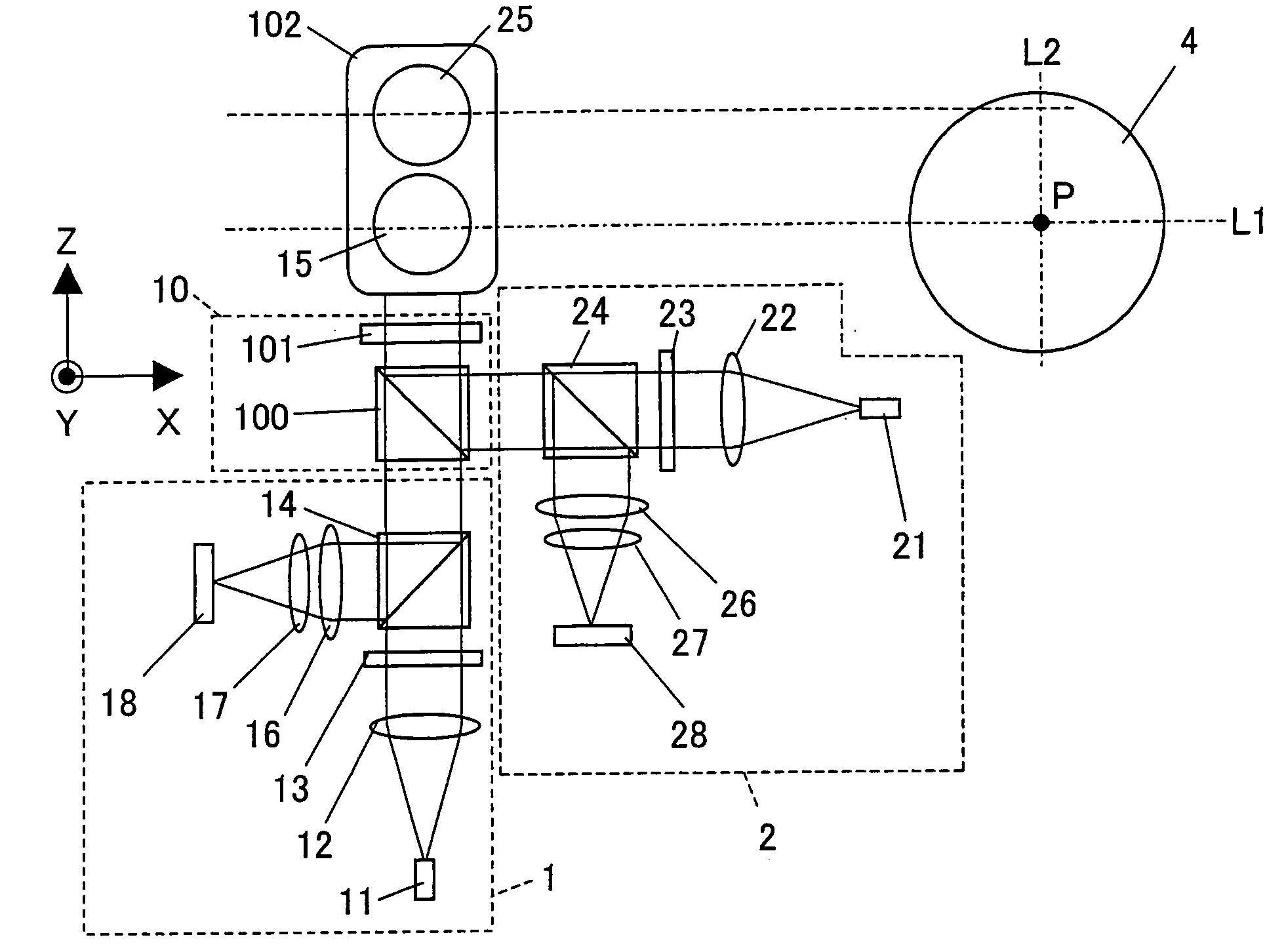
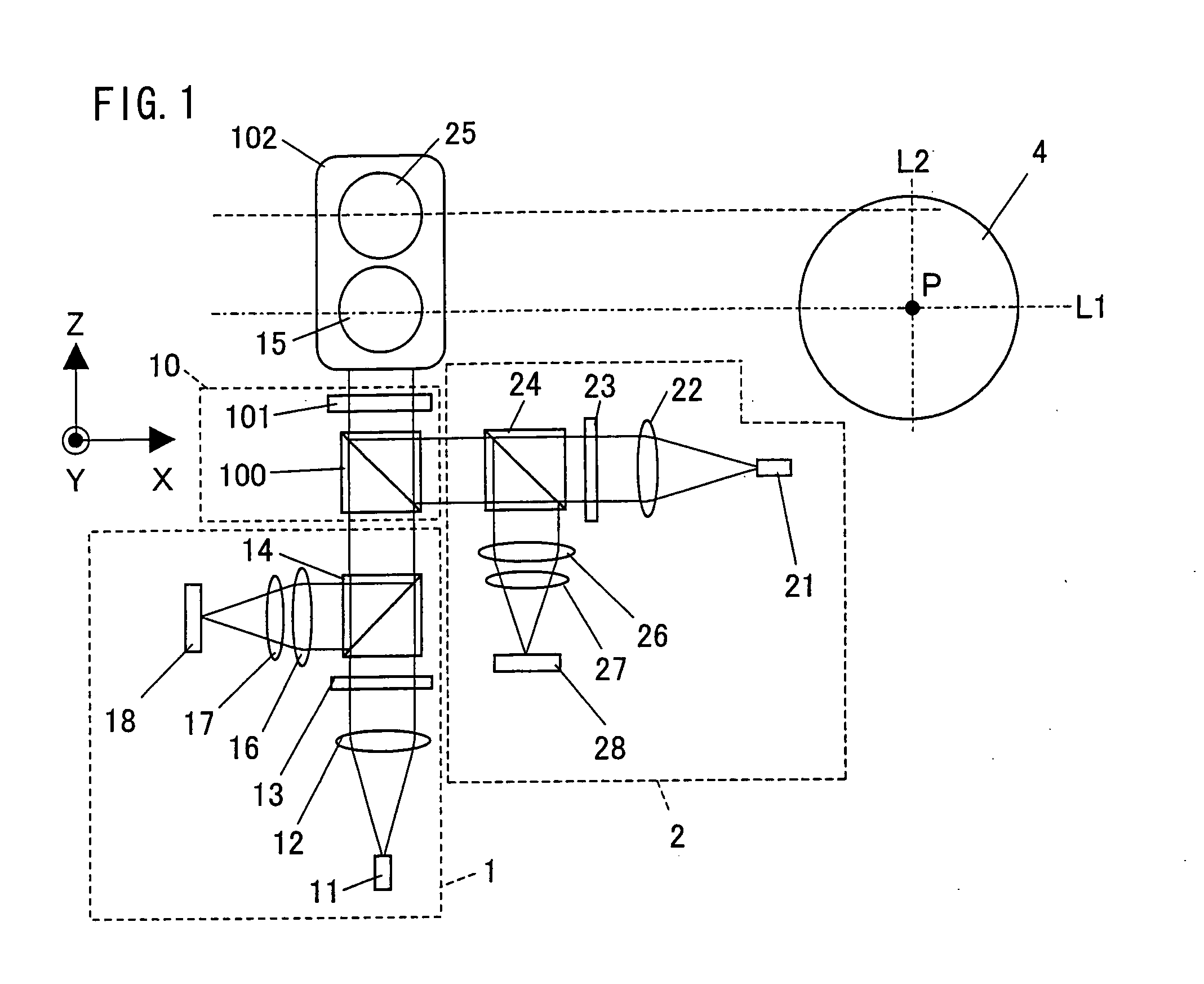
[0068]An optical pick-up of the present embodiment (hereinafter referred to as “present optical pick-up”) is incorporated into an optical information recording and reproducing apparatus that can write information in and read out information from a plurality of optical disks (optical recording media) such as a BD (Blu-ray Disc), a DVD, and a CD by irradiating the optical disks with beams. Specifically, the present optical pick-up is an optical pick-up, having a plurality of objective lenses and a plurality of light sources, which is capable of accurate tracking control.
[0069]An embodiment of the present invention will be described below with reference to FIGS. 1 through 7. FIG. 1 is a plan view schematically showing a structure of an optical information recording apparatus (hereinafter referred to as “present optical information recording and reproducing apparatus) including an optical pick-up of the present embodiment (hereinafter referred to as “present optical pick-up”).
[0070]As s...
embodiment 2
[0110]Another embodiment of the present invention will be described below with reference to FIGS. 8 through 10. FIG. 8 is a schematic diagram showing a light path of an optical pick-up according to the present embodiment (such an optical pick-up being hereinafter referred to as “present optical pick-up”). For convenience of explanation, members having the same functions as those shown in the drawings of Embodiment 1 are given the same reference numerals, and will not be described below. Furthermore, the positional relationship between a second objective lens and a first objective lens in the present embodiment is the same as in FIG. 1 of Embodiment 1, and therefore will not be described below.
[0111]As shown in FIG. 8, the present optical pick-up realizes stable tracking control by including a second optical system 2′ instead of the second optical system 2 of the optical pick-up of Embodiment 1. That is, the present optical pick-up differs from Embodiment 1 in that the present optica...
embodiment 3
[0124]Another embodiment of the present invention will be described below with reference to FIG. 11. FIG. 11 is a diagram schematically showing a structure of an optical pick-up of the present embodiment (such an optical pick-up being hereinafter referred to as “present optical pick-up”). For convenience of explanation, members having the same functions as those shown in the drawings of Embodiment 1 are given the same reference numerals, and will not be described below.
[0125]The present optical pick-up differs from Embodiment 1 in that the present optical pick-up further includes a third optical system 3 provided in a light path extending from the second optical system 2 to a common optical system 10′. The third optical system 3 converges a beam on a third optical disk by using a second objective lens 35. In the present optical pick-up, the second optical system 2 similarly converges a beam on the second optical disks by using the second objective lens 35. That is, in the present op...
PUM
 Abstract
Description
Claims
Application Information
 - R&D
- Intellectual Property
- Life Sciences
- Materials
- Tech Scout
- Unparalleled Data Quality
- Higher Quality Content
- 60% Fewer Hallucinations
Browse by: Latest US Patents, China's latest patents, Technical Efficacy Thesaurus, Application Domain, Technology Topic, Popular Technical Reports.
© 2025 PatSnap. All rights reserved.Legal|Privacy policy|Modern Slavery Act Transparency Statement|Sitemap|About US| Contact US: help@patsnap.com