Device for Aeration and Ventilation of a Fuel System

a fuel system and aeration technology, applied in the direction of machines/engines, separation processes, filtration separation, etc., can solve problems such as leakage in the fuel system, and achieve the effect of compact and convenient operation

Active Publication Date: 2011-07-28
AUDI AG
View PDF9 Cites 5 Cited by
  • Summary
  • Abstract
  • Description
  • Claims
  • Application Information

AI Technical Summary

Benefits of technology

[0007]A device of this type for aeration and ventilation of a fuel system of a motor vehicle has a pipe union for connecting the device to the fuel system. This pipe union is connected to a three-way valve by means of a connecting element and can be fluid-connected alternately to an air inlet opening or an air outlet opening of the device via the three-way valve. In the flow path between the three-way valve and the air inlet opening, there is a filter element to remove particles from the intaken air. The filter element, the connecting element, and the three-way valve are accommodated in a common housing so that an especially compact and thus space-saving device is obtained which can be made available as a pre-assembled mounted module.
[0009]In one preferred embodiment of the invention, the three-way valve is designed as a passive flap valve. Therefore, active components can be omitted; this constitutes especially high fail-safe performance and operational reliability of the ventilation process. The passive flap valve changes its position depending on the flow and pressure conditions. If an overpressure prevails on the side of the pipe union, the three-way valve clears an air path to the air outlet opening and at the same time closes the air inlet opening. Air flowing into the pipe union from the fuel system can therefore escape through the air outlet opening to the environment.

Problems solved by technology

If the overpressure cannot be built up or if the overpressure diminishes again too quickly, there is a leak in the fuel system.

Method used


Image

  • Device for Aeration and Ventilation of a Fuel System
  • Device for Aeration and Ventilation of a Fuel System
  • Device for Aeration and Ventilation of a Fuel System

Examples


Embodiment Construction

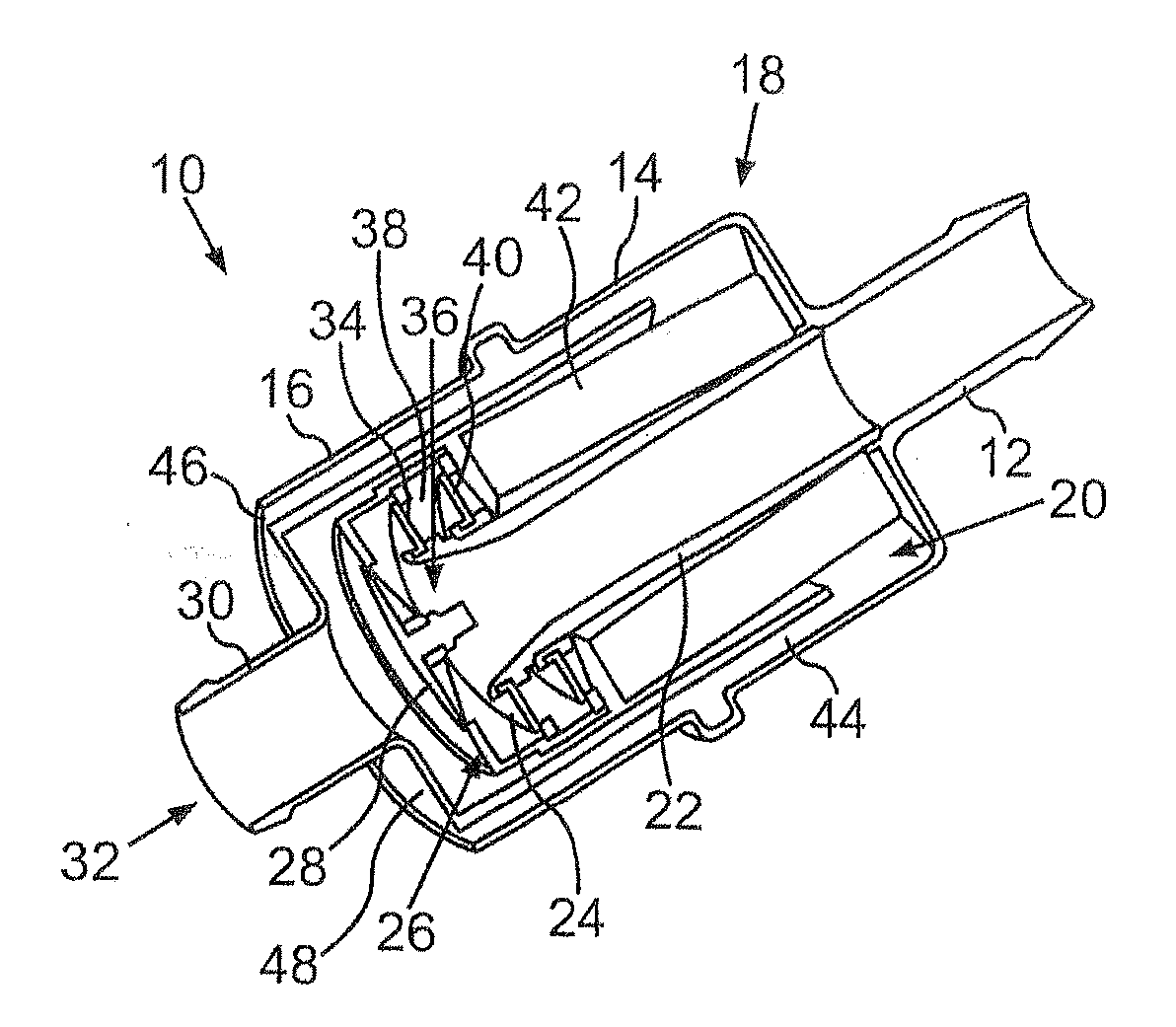
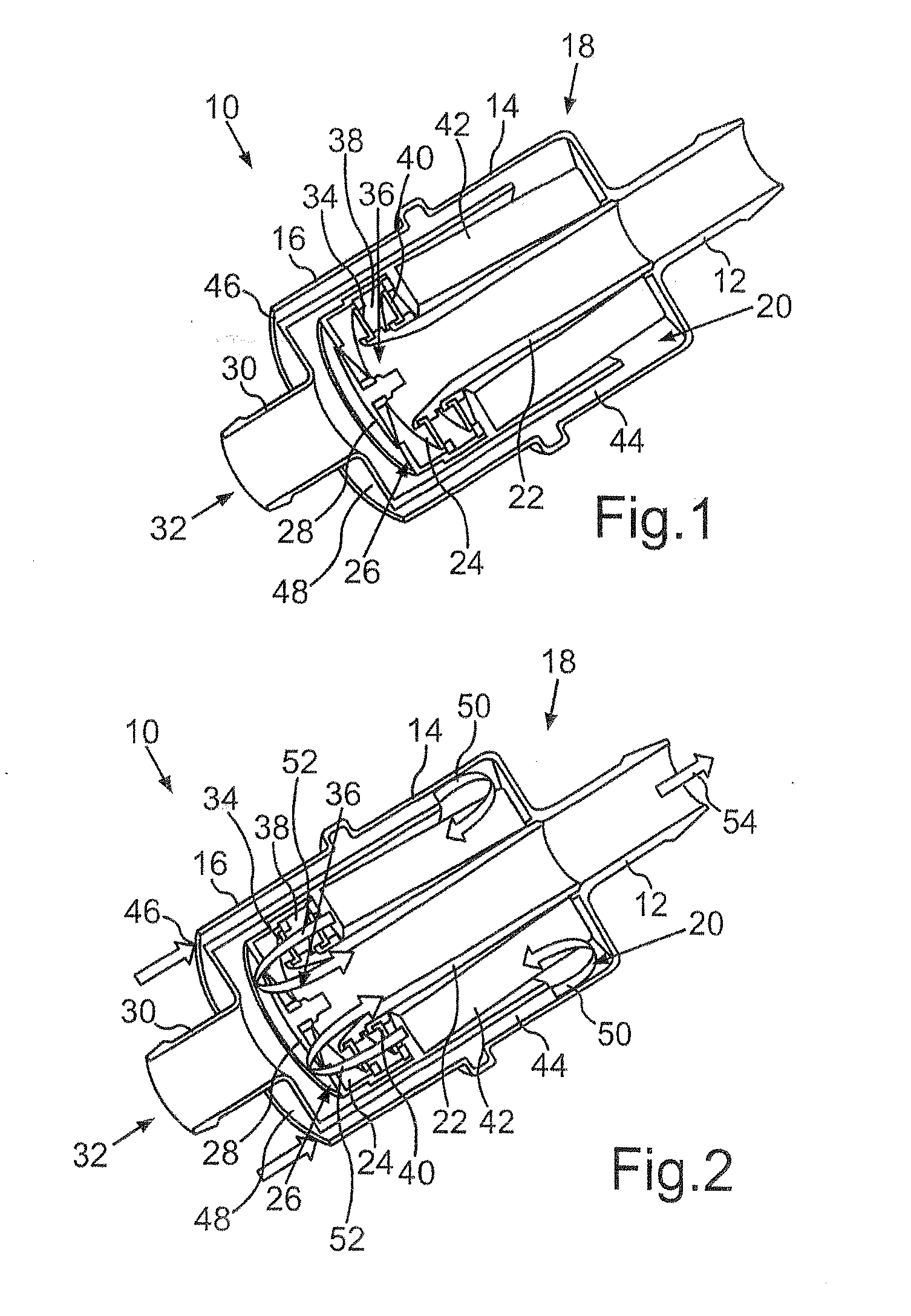
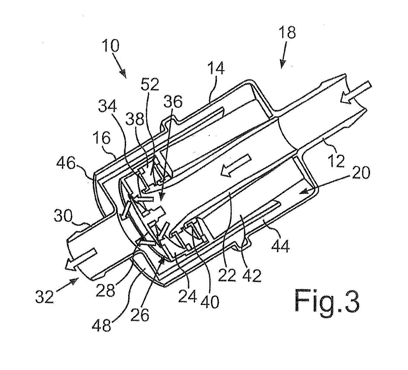
[0016]A device designated as a whole as 10 for aeration and ventilation of a fuel system of a motor vehicle comprises a pipe union 12 via which it can be connected to the fuel system. Typically, a hose is connected to the pipe union 12 and to a leak diagnosis pump of the motor vehicle. The pipe union 12 is made integral with one housing part 14 which, together with another housing part 16, forms the housing 18 of the device 10. The housing 18 is made cylindrical and is attached coaxially to the pipe union 12.

[0017]In the interior 20 of the housing 18, a pipe 22 is connected to the pipe union 12. The pipe 22 discharges into a valve chamber 24 of a three-way valve 26. The three-way valve 26 is made as a flap valve. A first valve flap 28 of the three-way valve borders the valve chamber 24 of another connecting sleeve 30, which discharges into the air outlet opening 32.

[0018]The valve seat of the valve flap 28 is designed such that the valve flap 28 is closed when a higher pressure prev...


PUM

PropertyMeasurementUnit
pressureaaaaaaaaaa
volatilityaaaaaaaaaa
timeaaaaaaaaaa

Abstract

The invention relates to a device for aeration and ventilation of a fuel system of a motor vehicle, with a pipe union for connecting the device to the fuel system, the pipe union being connected via a connecting element to a three-way valve via which the pipe union can be fluid-connected alternately to an air inlet opening or an air outlet opening of the device. Furthermore, there is a filter element which is located in the flow path between the air inlet opening and the three-way valve. The filter element, the three-way valve, and the connecting element are accommodated in a common housing. An especially compact and space-saving device is devised by the integration of the three-way valve, connecting element, and filter element into one unit.

Description

[0001]The invention relates to a device for aeration and ventilation of a fuel system of a motor vehicle.BACKGROUND OF THE INVENTION[0002]As a result of the volatility of gasoline and diesel fuels, in the fuel tanks of motor vehicles fuel vapors form which must be dissipated to prevent the generation of overpressure in the fuel tank. For reasons of emission prevention, the dissipated fuel vapors are generally routed through an activated charcoal filter which absorbs the volatile hydrocarbons. The remaining air is released into the environment.[0003]In order to facilitate the removal of fuel from the fuel tank, it must be possible at the same time to aerate the fuel tank. Many motor vehicles moreover have devices for monitoring the tightness of the fuel tank so that leaks can be detected early. For purposes of leak diagnosis, air is conventionally pumped into the fuel tank by means of a pump until a specified overpressure arises. If the overpressure cannot be built up or if the overp...

Claims


Application Information

Patent Timeline
Patent Type & Authority Applications(United States)
IPC IPC(8): B01D35/01B01D35/02
CPCF02M25/0854F02M25/0836B01D46/0087B01D46/0089B60K15/03519F16K17/19
Inventor KALAUCH, GERD
Owner AUDI AG
Why Eureka
Try Eureka