Vibration wave motor

a technology of vibration wave and motor, which is applied in the direction of generator/motor, electrical apparatus, electric/electrostriction/magnetostriction machines, etc., can solve the problems of unstable character of vibration wave motor, and achieve the effect of less expensive configuration

Active Publication Date: 2016-12-01
CANON KK
View PDF4 Cites 2 Cited by
  • Summary
  • Abstract
  • Description
  • Claims
  • Application Information

AI Technical Summary

Benefits of technology

The invention provides a vibration wave motor that can stably press with a compact and less expensive configuration. This is achieved by preventing the contact position between the pressing member and the pressing force transmitting member from shifting.

Problems solved by technology

However, in the prior art disclosed in the Japanese Patent Application Laid-Open No. 2014-212682, there has been a concern that since a configuration is not sufficient to restrict pressing force by the pressing member in the pressing direction, a contact position between the pressing member and the pressing force transmitting member is shifted.
If the contact portion is shifted, since uniform pressing to the vibrator cannot be effected, a new concern arises that a characteristic of the vibration wave motor is not stable.

Method used


Image

  • Vibration wave motor
  • Vibration wave motor
  • Vibration wave motor

Examples


Embodiment Construction

[0024]Basic embodiments to which the present invention is applied will be specifically described with reference to the accompanying drawings. In the drawings, the same components are denoted by the same reference numerals. It is needless to say that the following embodiments will be exemplary explained and the invention is not limited thereto.

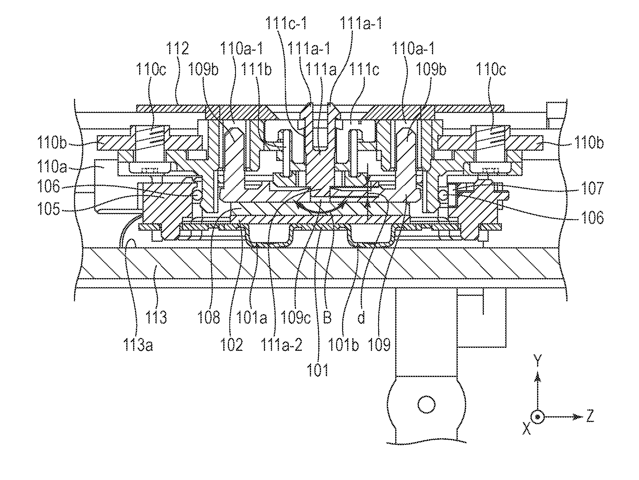
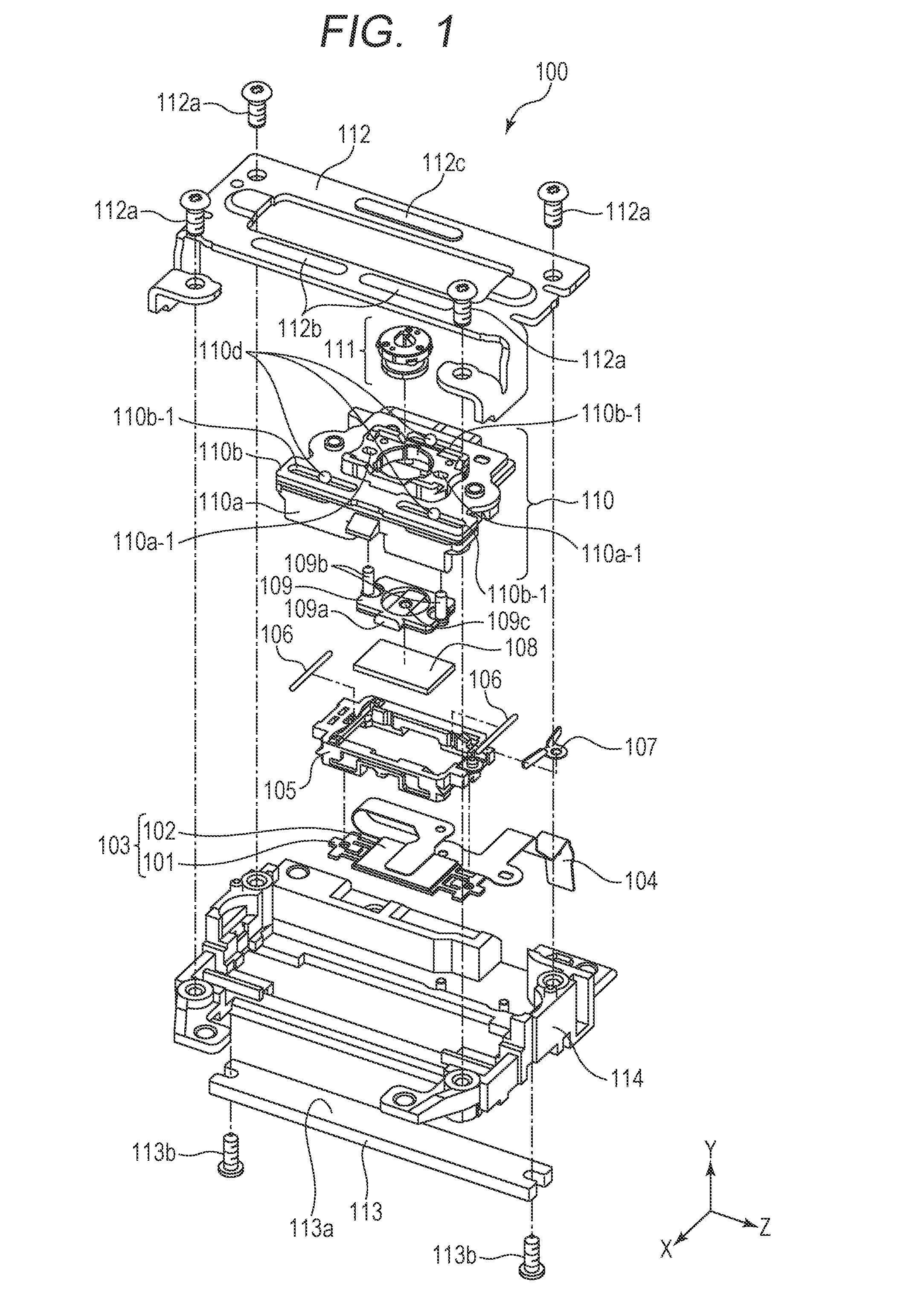
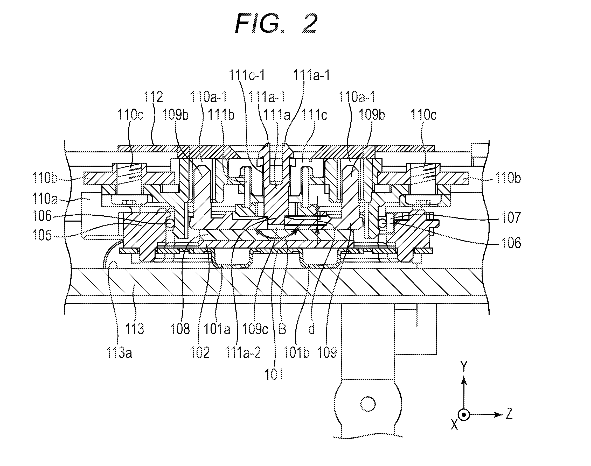
[0025]FIG. 1 is an exploded perspective view illustrating a vibration wave motor. FIG. 2 is a cross sectional view of the vibration wave motor in FIG. 1 taken along a plane perpendicular to an X-axis. In FIGS. 1 and 2, when an XYZ coordination system is defined as illustrated, FIG. 2 is a cross sectional view illustrating a central portion taken along a plane perpendicular to the X-axis in a state where the vibration wave motor in FIG. 1 is assembled. A structure of the vibration wave motor will be explained using FIGS. 1 and 2. It is noted that a Y-axis direction illustrated in FIG. 1 is a pressing direction by a pressing member 111 to be desc...


PUM


Abstract

A vibration wave motor includes: a vibrator including a vibration plate and a piezoelectric element; a friction member frictionally contacting the vibrator; a pressing member generating a pressing force to bring the vibrator in frictional contact with the friction member; and a pressing force transmitting member between the vibrator and the pressing member to transmit the pressing force to the vibrator. The vibrator and the friction member move in a relative movement direction by an elliptical vibration, and the pressing force transmitting member includes: an engagement portion formed near a contact portion with the pressing member and engaged with the pressing member; first restricting portion restricting movement in the relative movement direction; and a second restricting portion. restricting movement in a direction perpendicular to a pressing direction by the pressing member and the direction. The pressing force transmitting member is rotatably held with respect to the pressing member.

Description

BACKGROUND OF THE INVENTION[0001]1. Field of the Invention[0002]The present invention relates to a vibration wave motor to be employed in an optical device or the like.[0003]1. Description of the Related Art[0004]Conventionally, there has been known technology, as this type of the vibration wave motor, for moving the vibrator and a friction member relatively by bringing the vibrator that causes (ultrasonic) vibration cyclically in frictional contact with a friction member. An example of this vibration wave motor that is configured in a linear motion type and is used for linear motion focus drive is disclosed in the Japanese Patent Application Laid-Open No. 2014-212682.[0005]The prior art disclosed in the above-mentioned Japanese Patent Application Laid-Open No. 2014-212682 includes a pressing member for generating pressing force to bring the vibrator in frictional contact with a pressing force transmitting member that transmits the pressing force between the vibrator and the pressin...

Claims


Application Information

Patent Timeline
IPC IPC(8): H02N2/00
CPCH02N2/0055H02N2/026
Inventor YAMASAKI, RYO
Owner CANON KK
Why Eureka
Try Eureka