Encoder and data transmission method

a technology of encoder and data transmission method, which is applied in the direction of computer control, program control, instruments, etc., can solve the problems of inability to complete position data generation in time, expensive a/d converters and the like capable of high-speed processing, etc., to shorten the calculation time of the rotational position, shorten the time for generating position data of the encoder, and improve the responsiveness of the encoder

Active Publication Date: 2020-02-13
FANUC LTD
View PDF4 Cites 2 Cited by
  • Summary
  • Abstract
  • Description
  • Claims
  • Application Information

AI Technical Summary

Benefits of technology

The present invention aims to provide a less expensive solution for exchanging signals between a control device and an encoder in a shorter communication cycle. This helps to improve the responsiveness of the encoder without the need for expensive equipment. The goal is to allow for quicker position data generation and transmission.

Problems solved by technology

In this case, the time for generating the position data of the encoder must be shortened, so that there may occur a problem that generation of the position data cannot be completed in time before the start of transmission of the position data.
To deal with this situation, an expensive A / D converter and the like capable of executing high-speed processing may be required to shorten the calculation time of the rotational position and the like.

Method used


Image

  • Encoder and data transmission method
  • Encoder and data transmission method
  • Encoder and data transmission method

Examples


embodiment

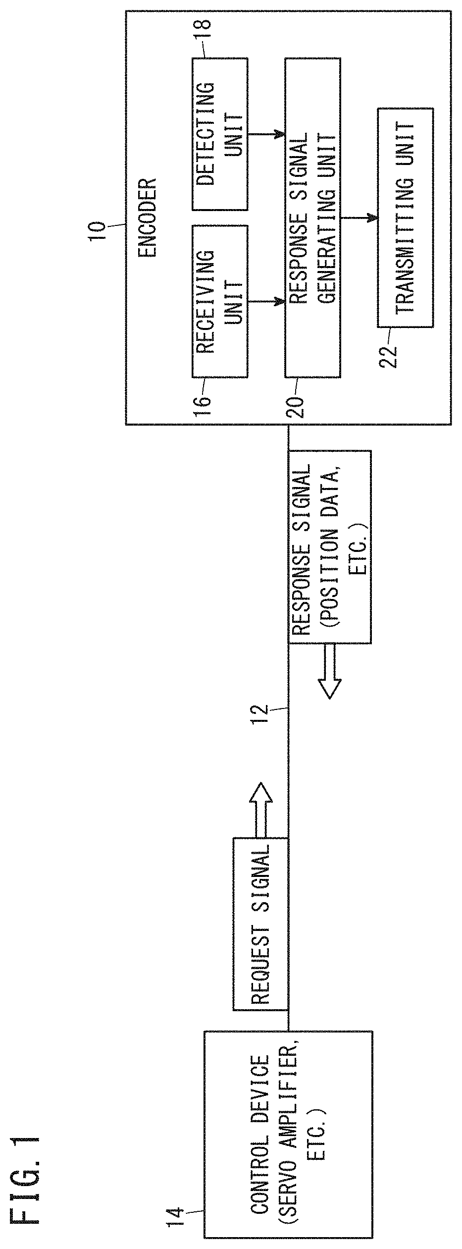
[0016]FIG. 1 is a diagram for explaining the function of an encoder 10 according to the present embodiment. The encoder 10 is connected to a control device 14 such as a servo amplifier via a transmission circuit 12 that transmits various pieces of information by serial communication. When the encoder 10 receives a request signal indicating a request for position data from the control device 14, the encoder 10 calculates the rotational position etc., of a motor, which is one of the measurement targets, and transmits a response signal including the position data indicating the calculated position to the control device 14. Exchange (transmitting and receiving) of the request signal and the response signal between the encoder 10 and the control device 14 is performed in a fixed communication cycle. Hereinbelow, the rotational position or the like of the motor to be measured is also referred to as the position.

[0017]In order to realize the above-described function, the encoder 10 include...


PUM


Abstract

An encoder that receives, from a control device, a request signal for requesting position data and transmits a response signal including the position data to the control device by serial communication, at a predetermined communication cycle, includes: a response signal generating unit configured to generate a response signal including the position data and associated data associated with the position data; and a transmitting unit configured to transmit the generated response signal. The transmitting unit is configured to transmit the associated data prior to transmission of the position data when transmitting the response signal.

Description

CROSS-REFERENCE TO RELATED APPLICATION[0001]This application is based upon and claims the benefit of priority from Japanese Patent Application No. 2018-149078 filed on Aug. 8, 2018, the contents of which are incorporated herein by reference.BACKGROUND OF THE INVENTIONField of the Invention[0002]The present invention relates to an encoder and a data transmission method.Description of the Related Art[0003]As disclosed in Japanese Laid-Open Patent Publication No. 2008-090825, in serial communication between an encoder (position detector) for detecting a rotation angle or the like (position) of a motor and a control device (controller) such as a servo amplifier for controlling the encoder, when the encoder receives a request signal (transmission request) involving a request for position data indicative of a rotational position or the like, from the control device, the encoder transmits a response signal including position data (positional information) to the control device.SUMMARY OF TH...

Claims


Application Information

Patent Timeline
Patent Type & Authority Applications(United States)
IPC IPC(8): H04B1/04G05B19/402
CPCG05B2219/36489H04B1/04G05B19/402G01D5/24457G05B19/0428
Inventor HAYASHI, TAKUROU
Owner FANUC LTD
Why Eureka
Try Eureka