
Pneumatic tire

a technology of pneumatic tires and tires, applied in the field of pneumatic tires, can solve the problems of the decline in the stability of steering, and achieve the effect of improving the stability of steering

Active Publication Date: 2011-07-28
THE YOKOHAMA RUBBER CO LTD
View PDF4 Cites 9 Cited by
  • Summary
  • Abstract
  • Description
  • Claims
  • Application Information

AI Technical Summary

Benefits of technology

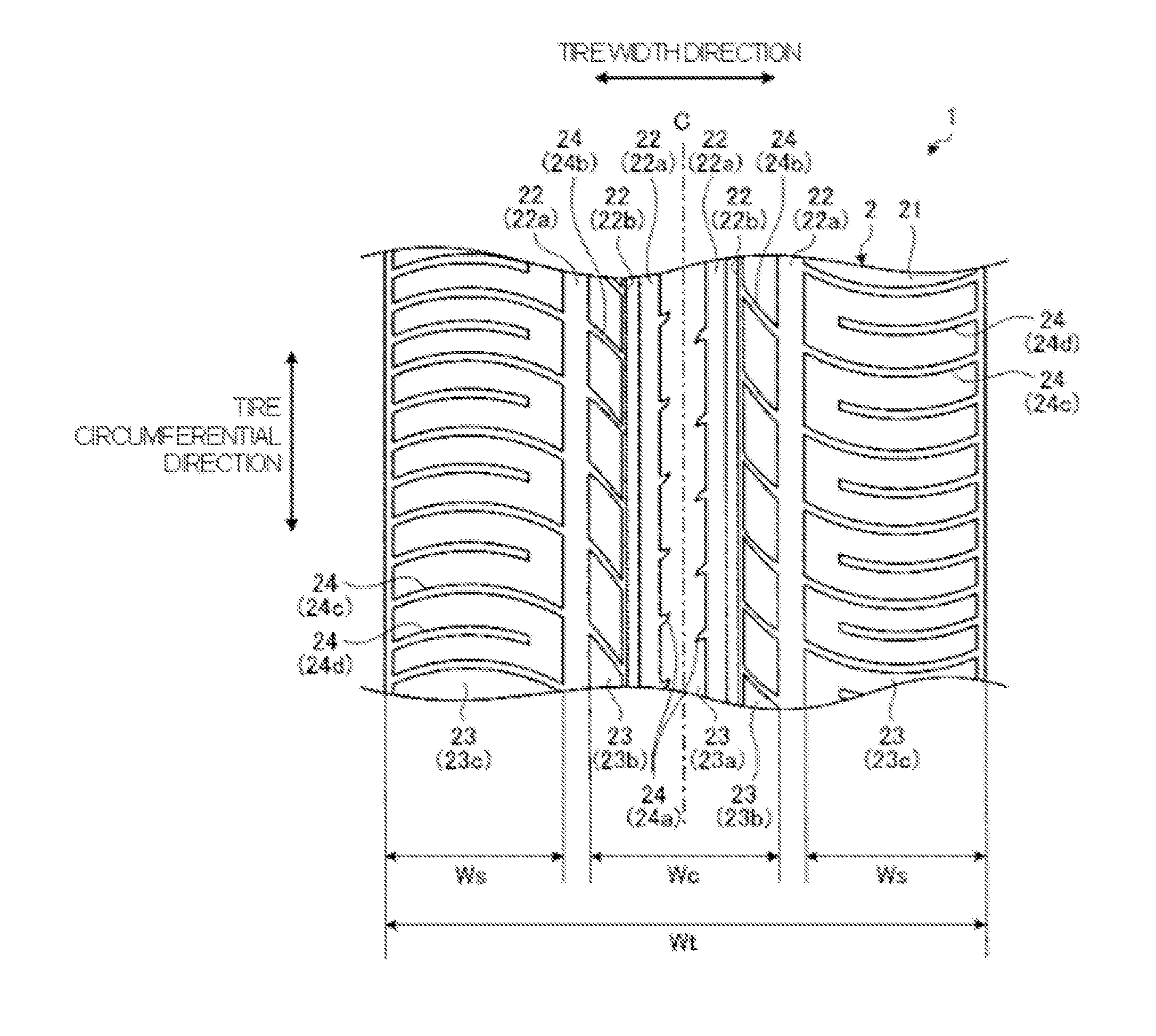
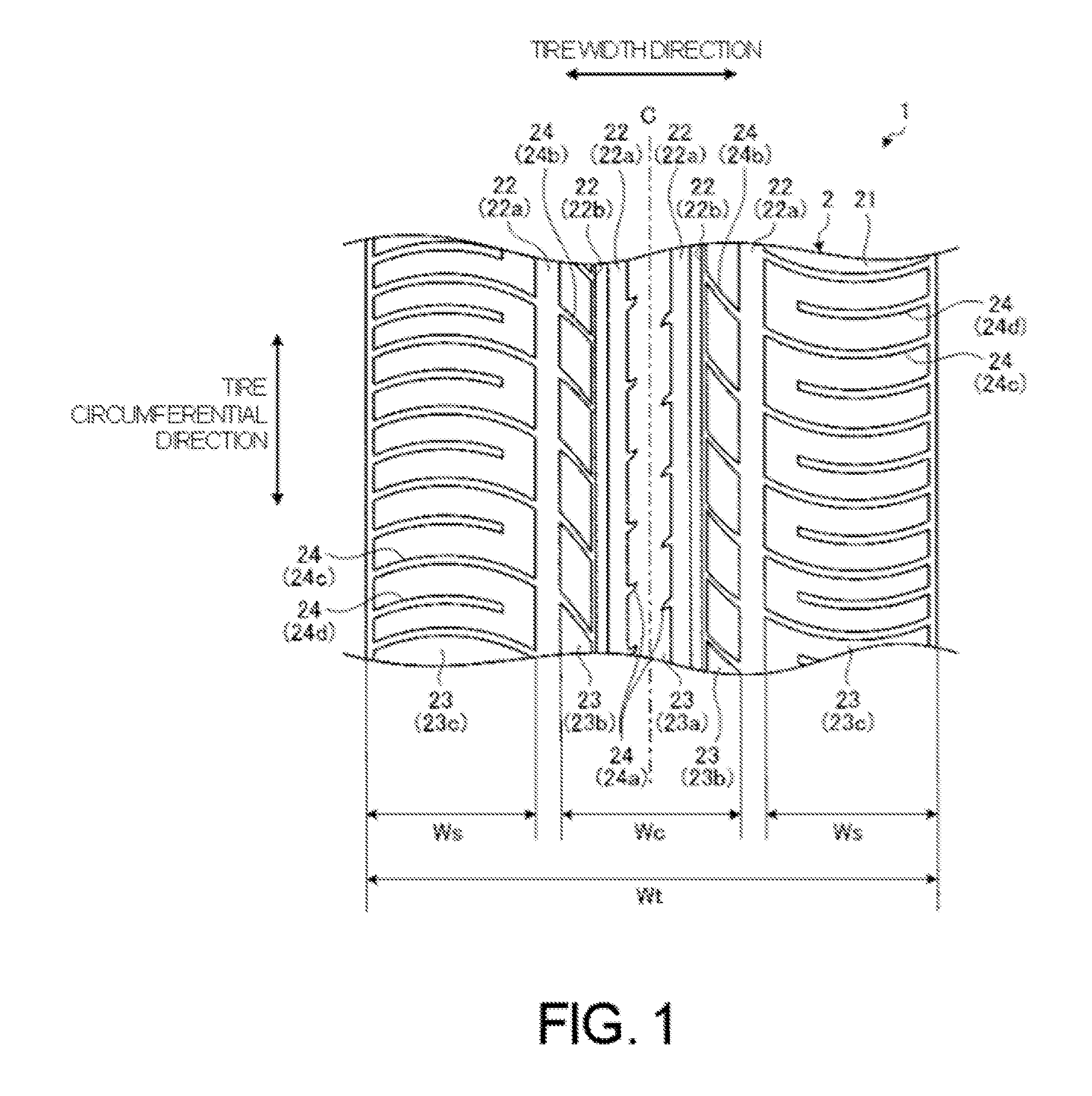
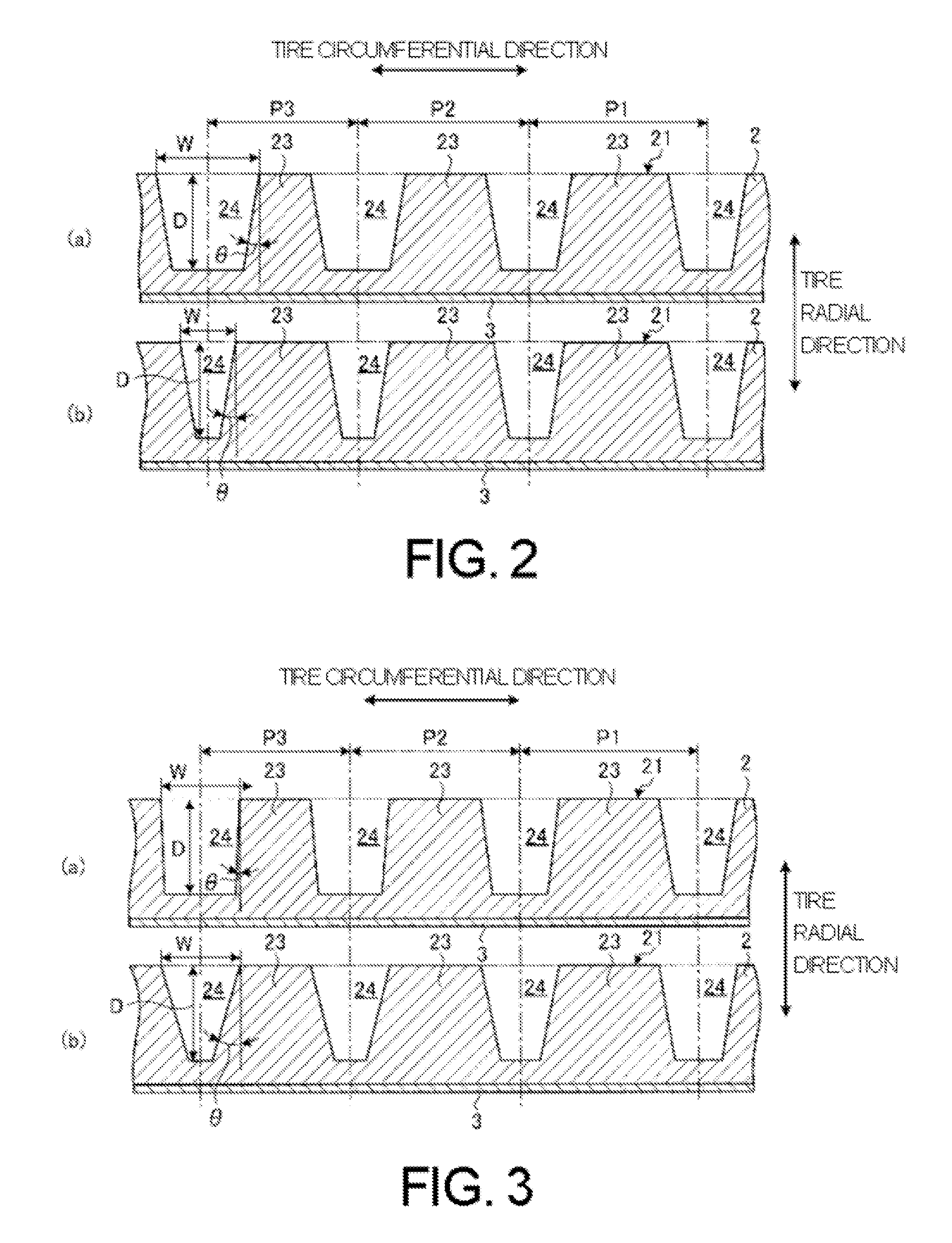
[0010]According to an example of a pneumatic tire, as the pitch decreases in the shoulder regions of the tread portion, the volume ratio of the lateral grooves with respect to the pitch volume thereof is increased. Therefore, compared to a case where a variable pitch construction is employed in which the volume of the lateral grooves is constant, because the volume ratio of the lateral grooves increases the smaller the pitch of land portions having small volumes becomes, the amount of vulcanized rubber pressed in during tire formation at each pitch (circumferential direction) is made uniform. As a result, uniformity in the shoulder regions, which, if poor, can be a cause of vibration being generated in a steering wheel or a vehicle, can be improved. In one example of a pneumatic tire, as the pitch decreases in the center region of the tread portion, the volume ratio of the lateral grooves with respect to the pitch volume thereof is decreased. Therefore, compared to a case where a variable pitch construction is employed in which the volume of the lateral grooves is constant, because the volume ratio of the lateral grooves decreases the smaller the pitch of land portions having small volumes becomes, the stiffness of the land portions at each pitch (circumferential direction) is made uniform. As a result, portions of the land portions in the center region experiencing extreme decreases in stiffness will be eliminated and, therefore, steering stability can be improved. Therefore, steering stability can be improved while uniformity is maintained.
[0017]With the pneumatic tire of the present technology, steering stability can be improved while uniformity is maintained in a pneumatic tire employing a variable pitch construction.

Problems solved by technology

When a stiffness of land portions in a center region adjacent to a tire equatorial plane declines, there is a tendency for steering stability to decline.

Method used


Image

  • Pneumatic tire
  • Pneumatic tire
  • Pneumatic tire

Examples


examples

[0045]In the examples, performance tests for steering stability (initial response) and uniformity were performed on a plurality of types of pneumatic tires under different conditions (see FIG. 5).

[0046]An evaluation method for steering stability included assembling pneumatic tires having a tire size of 175 / 65R15 on regular rims (a “standard rim” defined by the Japan Automobile Tire Manufacturers Association Inc. (JATMA), a “design rim” defined by the Tire and Rim Association, Inc. (TRA), or a “measuring rim” defined by the European Tyre and Rim Technical Organisation (ETRTO)). The pneumatic tires were inflated to an air pressure of 230 kPa and mounted on a test vehicle (1.3 liter class hatchback passenger vehicle, made in Japan). Then, a sensory evaluation of initial response by a driver when the test vehicle changed traveling lanes while traveling on a straight test course at 100 km / h was used to evaluate steering stability using a conventional example as a benchmark. Here, average...


PUM


Abstract

A pneumatic tire having a tread portion including land portions formed by vertical grooves provided in a tire circumferential direction and lateral grooves provided so as to intersect with the vertical grooves, the lateral grooves being disposed in the tire circumferential direction having a plurality of pitches P1, P2, and P3, wherein in a shoulder region of the tread portion, as a pitch decreases a volume ratio of the lateral grooves with respect to a pitch volume thereof increases; and, in a center region of the tread portion, as a pitch decreases the volume ratio of the lateral grooves with respect to a pitch volume thereof decreases.

Description

PRIORITY CLAIM[0001]This application is based upon and claims the benefit of priority from Japanese Patent Application No. 2010-015096, filed Jan. 27, 2010, the entire contents of which is incorporated herein by reference.BACKGROUND[0002]1. Technical Field[0003]The present technology relates to a pneumatic tire employing a variable pitch construction, the pneumatic tire having enhanced steering stability and uniformity.[0004]2. Related Art[0005]Pneumatic tires exist that have tread patterns in tread portions formed from vertical grooves provided in a circumferential direction and lateral grooves provided so as to intersect these vertical grooves. In such a pneumatic tire, by employing a variable pitch construction, wherein the lateral grooves are provided in the tire circumferential direction with a plurality of pitches, pitch noise generated in the tire circumferential direction is dispersed over a wide range of frequencies, leading to an improvement in noise properties.[0006]For e...

Claims


Application Information

Patent Timeline
Patent Type & Authority Applications(United States)
IPC IPC(8): B60C11/00
CPCB60C11/0306B60C2011/0367B60C2011/0365B60C11/033B60C11/0318B60C11/0309B60C2011/0369
Inventor MORITA, KENICHI
Owner THE YOKOHAMA RUBBER CO LTD
Learn More