Eureka AIR delivers breakthrough ideas for toughest innovation challenges, trusted by R&D personnel around the world.

Genset engine with an electronic fuel injection system integrating electrical sensing and crank position sensing

a technology of electronic fuel injection and generator engine, which is applied in the direction of electrical control, process and machine control, instruments, etc., to achieve the effect of optimizing spark timing, optimal engine performance and efficiency

Active Publication Date: 2011-07-28
CUMMINS POWER GENERATION
View PDF8 Cites 24 Cited by
  • Summary
  • Abstract
  • Description
  • Claims
  • Application Information

AI Technical Summary

Benefits of technology

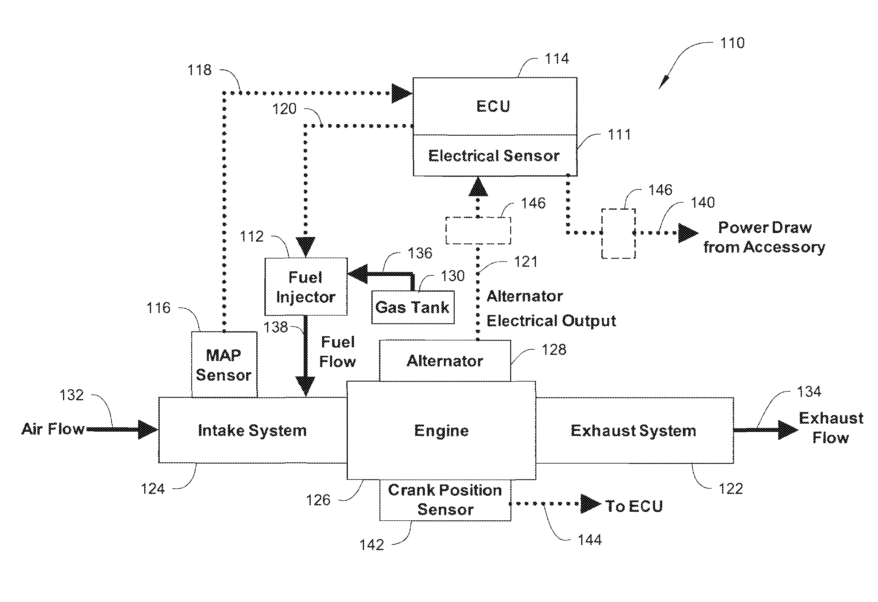
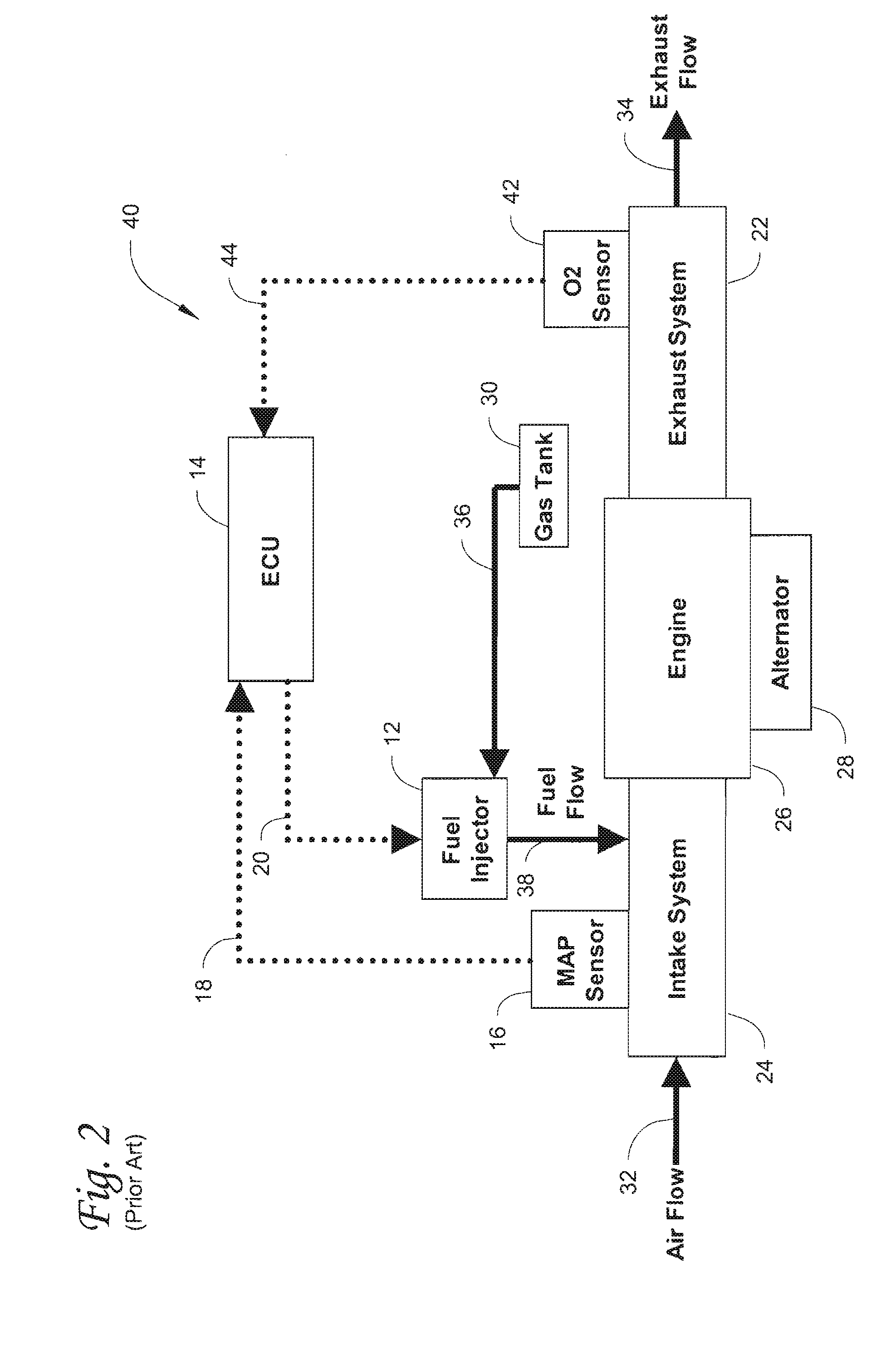
The patent describes an open loop EFI system with an electrical sensor and crank position sensor for a genset engine. This system allows for optimal spark timing and fuel injection based on engine speed and load. The electrical sensor and crank position sensor work together with data from other sensors to determine the optimal air-to-fuel ratio and spark timing. This system can be used on any internal combustion engine and can improve engine performance and efficiency. The closed loop EFI system also integrates an oxygen sensor to input data regarding exhaust gases, and the system takes into account oil temperature, coolant temperature, and other factors to determine when to use the oxygen sensor's information for closed loop operation. Overall, this patent describes a system that can optimize engine performance and efficiency on a genset engine, and can be used in various applications such as stand-alone engines for power generation or as a backup power source.

Problems solved by technology

The problem is that current genset engines are equipped with a simple ignition system that does not allow the controller to change spark timing.

Method used


Image

  • Genset engine with an electronic fuel injection system integrating electrical sensing and crank position sensing
  • Genset engine with an electronic fuel injection system integrating electrical sensing and crank position sensing
  • Genset engine with an electronic fuel injection system integrating electrical sensing and crank position sensing

Examples


Embodiment Construction

FIGS. 3-5 illustrate embodiments of an EFI system in accordance with inventive principles described herein. For example, an open loop EFI system with an electrical sensor and crank position sensor, or alternately a closed loop EFI system with an electrical sensor and crank position sensor, is described. The EFI system can be used on a genset engine or any type of internal combustion engine. A genset engine's exhaust emissions and general performance are a function of spark timing. Spark timing determines when the air-fuel mixture will be ignited. The ignition of the air-fuel mixture must be at precisely the right moment, the moment when the piston is at its optimal position, or emissions can increase and engine performance is compromised. The integration of an electrical sensor and crank position sensor on a genset engine provides optimal engine performance and efficiency when the power needs fluctuate due to increased or decreased load on the genset engine, for example at start up ...


PUM


Abstract

An open or closed loop EFI system, integrated on a genset engine or any internal combustion engine, with an electrical sensor and crank position sensor is described. Since a genset engine's exhaust emissions and general performance are a function of spark timing, integration of electrical and crank position sensors on a genset engine provides optimal engine performance and efficiency when the electrical draws fluctuate. The electrical sensor and crank position sensor send data to the electronic control unit (ECU), and this data is used to determine the optimal air-to-fuel ratio (AFR) and optimal spark timing. The ECU varies the spark timing in accordance with the speed and load of the engine and actuates the fuel injector to send the correct amount of atomized fuel to mix with the air flow to be combusted allowing the engine to meet performance.

Description

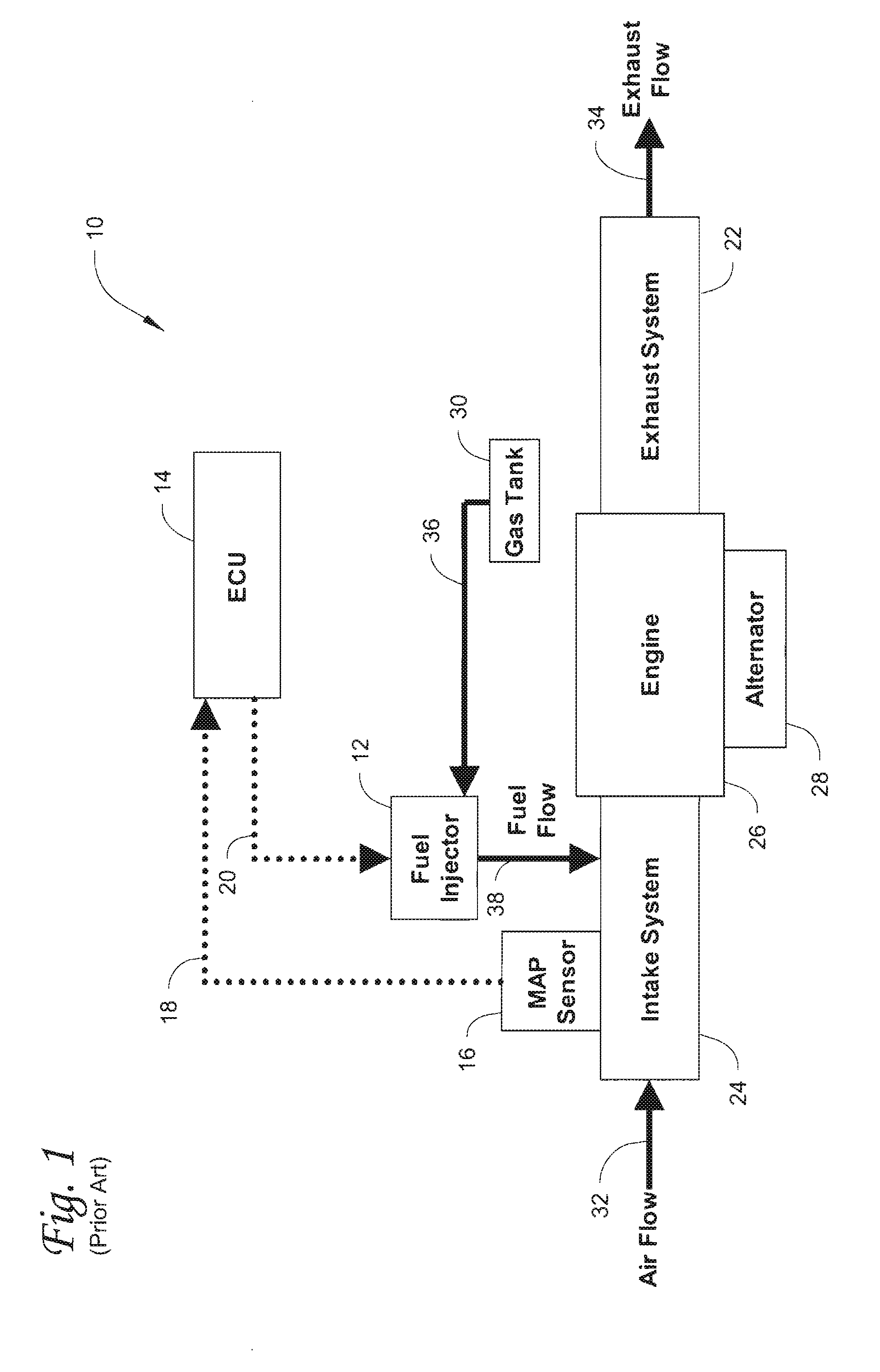
FIELDThis disclosure relates using open loop and, alternately, closed loop electronic fuel injection (EFI) systems with electrical sensing and crank position sensing on internal combustion engines, particularly in genset engines as one example. Various engine sensors, including for example air sensors, send signals to an electronic control unit (ECU) which in turn controls the fuel / air mixture to reach the requested relative air-to-fuel ratio (AFR) resulting in improved and efficient engine performance. The electrical sensor determines the amount of power being output by the alternator and the amount of power being drawn by the system to further calibrate the AFR. The crank position sensor determines the location of the piston in order to facilitate optimal spark timing. This information is provided to the ECU to control the AFR and control the spark timing to maintain optimal engine performance and efficiency.BACKGROUNDFuel injection systems are known and mix fuel with air in inter...

Claims


Application Information

Patent Timeline
Patent Type & Authority Applications(United States)
IPC IPC(8): F02M51/00F02D41/30
CPCF02D37/02F02D41/064F02D2200/0406F02D41/1488F02D41/1456
Inventor FALKOWSKI, DAVID T.PETERSON, JEFFREY D.ETHEN, MATTHEW J.KNIGHT, KRISTOPHER G.VANCALLIGAN, PETER J.
Owner CUMMINS POWER GENERATION
Why Eureka
Eureka Blog
Learn More