Hanger with an insulated hook

Inactive Publication Date: 2011-07-21
SANDER JR FR SCOTT +1
View PDF15 Cites 10 Cited by
  • Summary
  • Abstract
  • Description
  • Claims
  • Application Information

AI Technical Summary

Benefits of technology

[0013]Accordingly, several objects and advantages of our hanger are safety, speed, and adaptability to different shapes of metal decking.
[0014]Because our hanger is easy to install and move it will result in an increase in safety. Workers will not be tempted to hang cords from existing pipes and equipment whenever they need to quickly move to other areas. Our hanger, in the preferred and alternative embodiments, adjusts to different widths and may be installed into crevices of varying types of surfaces.
[0015]Also, workers will be safe from temp power cords hung from our screw-on insulated hooks. These hooks will not only insulate but also release the cords when “snagged” by passing forklifts. This releasing will leave cords undamaged and forklift driver simply puts cords back up on the hooks of our devices. Separating cords from all conductive materials will meet today's OSHA standards. And the ability of the insulated hooks to release cords will save on construction costs.

Problems solved by technology

Temporary power cords become damaged and unsafe when heavy construction traffic run them over.
The first is unsafe, the second is costly and sometimes unsafe, and the third is not adaptable to different types of surfaces.
According to OSHA, this is unsafe and against regulations because workers are constantly testing and continually working on this overhead equipment and pipes through all phases of the job.
These pipes and equipment are made of conductive materials and a simple cut or nick in a live temporary power cord results in an electrical short or surge that hurts or kills those working on these overhead systems.
Even current cordless hammer drills can only drill a few holes per charged battery into metal decking and concrete.
This alternative's disadvantage is that it involves constant drilling and re-drilling.
Resulting in anchoring many hangers for temp power cords costing extra money in labor and time.
However, the disadvantage of current plastic strapping is that when the power cords get pulled on accidentally by forklifts they do not “give” and let go of the cords.
The result is damage or destruction to the power cords.
Forklifts carrying loads high in the air often catch the power cords and put pressure and damage cords if the tie-wire hanger does not release the power cord.
The disadvantages of permanent home-made or purchased anchors and hangers are the cost in labor and time to put them in a constantly changing location staying ahead of temporary power needs for lighting and work.
Also, using tie-wire and or locking plastic straps are unsafe and cost extra money because they eventually destroy the power cords.
However, All of these temporary hangers will only fit on or into certain types and shapes of metal decking.
The disadvantage of the above temporary hangers are they require specific shaped and spaced metal decking.
Also, the climbing cams are very expensive.
The disadvantages of the first way mentioned is unsafe, the second is costly and also unsafe, and the third is not adaptable to different types of metal decks and can be costly.
This releasing will leave cords undamaged and forklift driver simply puts cords back up on the hooks of our devices.
No drilling and easy adjustment of our hanger will increase the speed and adaptability at which cords are moved and then placed at different locations overhead.

Method used


Image

  • Hanger with an insulated hook
  • Hanger with an insulated hook
  • Hanger with an insulated hook

Examples


Embodiment Construction

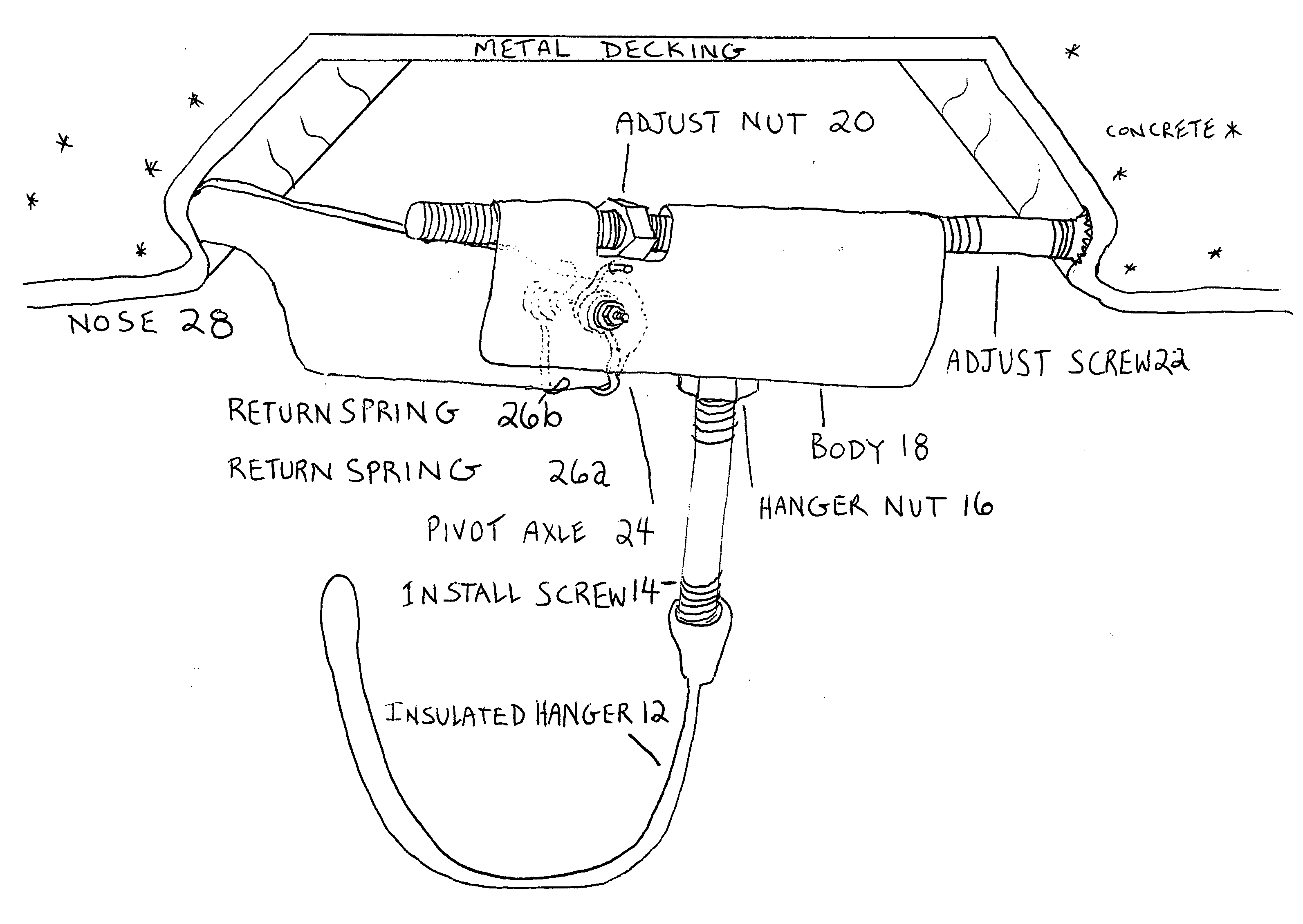
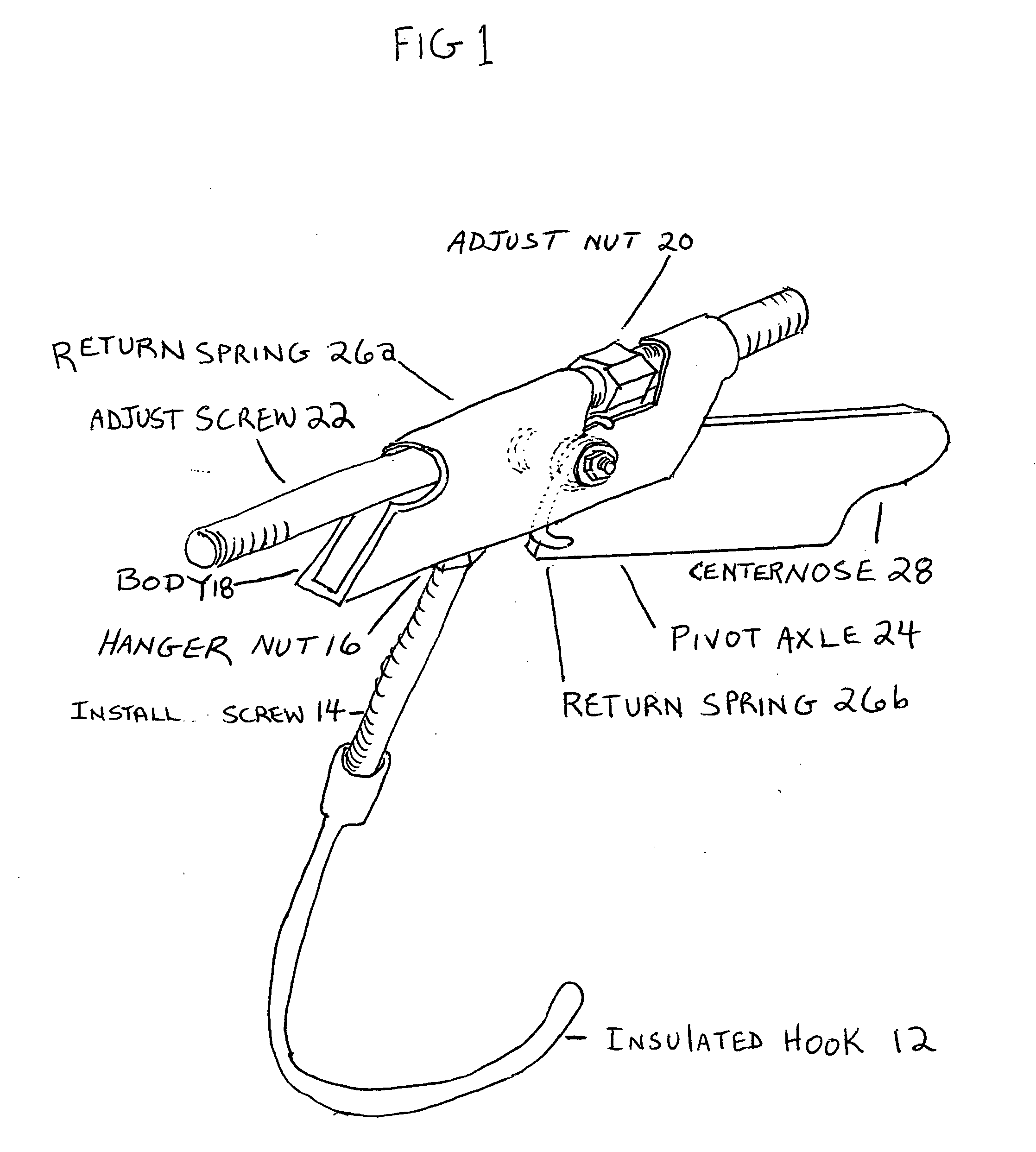
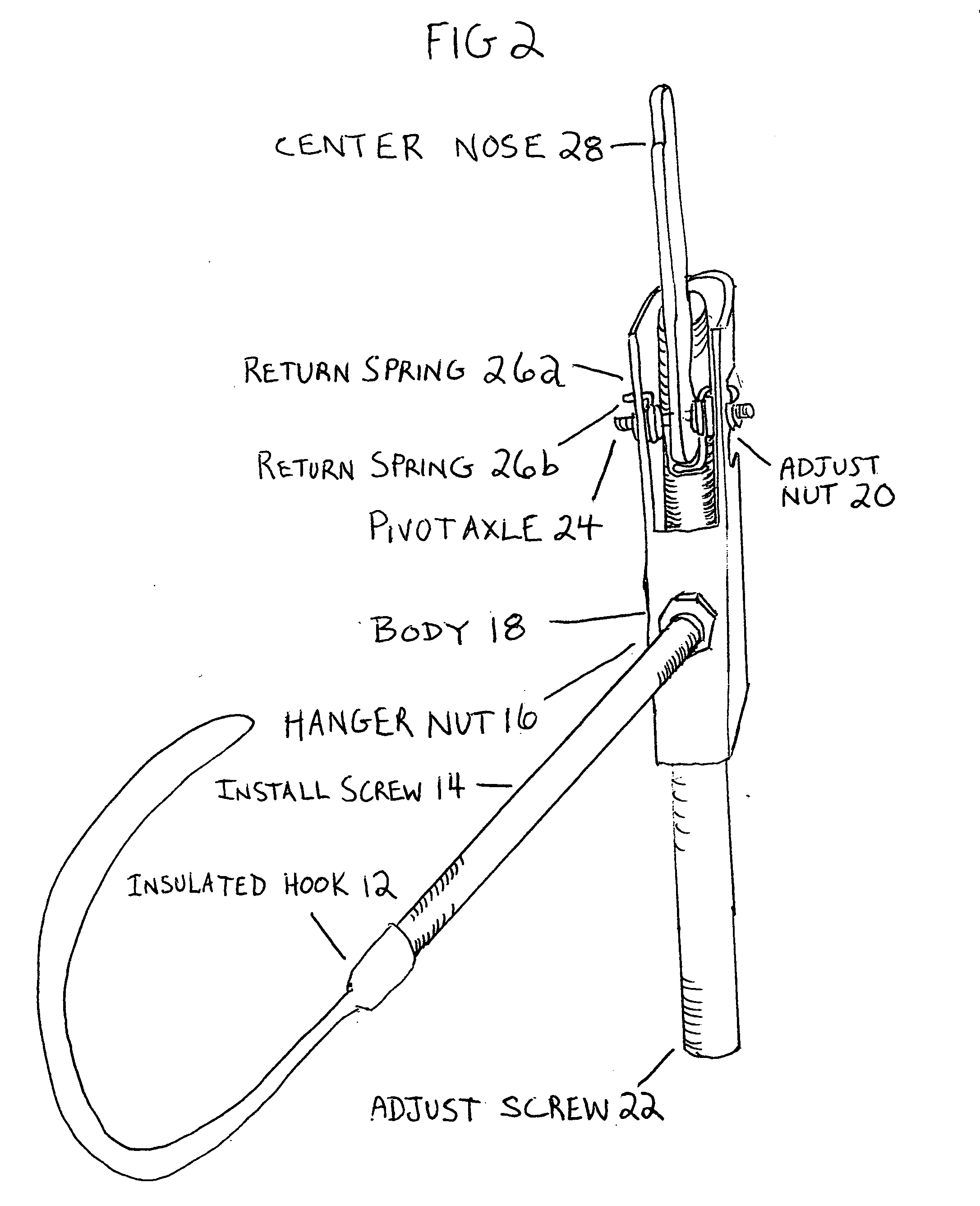
[0047]FIGS. 1 and 2 show a top and bottom perspective of the device. Insulated hook 12 is insulated and will be made of but not limited to, plastic, with a female screw receiving end adaptable to a standard piece of all-thread or install screw 14. Install screw 14 is a standard piece of all-thread cut to a desired length and will have hook 12 screwed on one end. The other end of install screw 14 will screw into hanger nut 16. Hanger nut 16 will be attached securely, for example by welding, to the bottom of body 18. The body 18 will envelope the adjust nut 20 and the adjust screw 22. Adjust screw 22 will be threaded into adjust nut 20 into and through the body 18. Body 18 will also house the toggle joint or pivot axle 24. Nose 28 will be attached to the body 18 by pivot axle 24. Wrapped around pivot axle 24 and anchored to the body 18 are the return springs 26a and 26b. The return springs 26a and 26b will be pre-tensioned and attached also to the nose 28.

OPERATION OF INVENTION

[0048]T...


PUM


Abstract

FIG. (1) and FIG. (2) show a top and bottom perspective of the device. Insulated Hook (12) is insulated and will be made of but not limited to, plastic, with a female screw receiving end adaptable to a standard piece of all-thread or install screw (14). Install screw ( )14 is a standard piece of all-thread cut to a desired length and will have hook (12) screwed on one end. The other end of install screw (14) will screw into hanger nut (16). Hanger nut (16) will be attached securely, for example by welding, to the bottom of body (18). The body (18) will envelope the adjust nut (20) and the adjust screw (22). Adjust screw (22) will be threaded into adjust nut (20) into and through the body (18). Body (18) will also house the toggle joint or pivot axle (24). Nose (28) will be attached to the body (18) by pivot axle (24). Wrapped around pivot axle (24) and anchored to the body (18) are the return springs (26a) and (26b). The return springs (26a) and (26b) will be pre-tensioned and attached also to the nose (28).In an additional embodiment right nose (30) and left nose (32) are connected to center nose (28) by connector axle (34). This embodiment will stabilize and increase ease of install of the device.FIGS. 1-9 are only examples of the possibilities of the hanger. And the device should not be limited to the above illustrated forms. Other applications and designs may become apparent as the above description, operation, and the drawings attached are studied by those in safety, manufacturing, construction, and related fields.

Description

CROSS-REFERENCE TO RELATED APPLICATIONS[0001]Non-applicableFEDERALLY SPONSORED RESEARCH[0002]Non-applicableSEQUENCE LISTING OR PROGRAM[0003]Non-applicableBACKGROUND OF THE INVENTION[0004]An improved mechanism for hanging temporary items from a variety of opposing surfaces.BACKGROUNDPrior Art[0005]Temporary power cords become damaged and unsafe when heavy construction traffic run them over. During construction, forklifts and hand trucks are constantly crossing the path of power cords that are used for lighting and for work. This is why OSHA requires the suspending of all power cords overhead. Currently, cords may be hung in three ways. The first is unsafe, the second is costly and sometimes unsafe, and the third is not adaptable to different types of surfaces.[0006]The first method suspends temporary power cords from existing sprinkler pipes, plumbing, ductwork, or other equipment attached to the underside of the metal decking of each floor. According to OSHA, this is unsafe and agai...

Claims


Application Information

Patent Timeline
IPC IPC(8): F16L3/24
CPCF16L3/24E04B9/18F16L3/243F16L3/2431
Inventor SANDER, JR., FRANK SCOTTHAGAN, DANIEL SCOTT
Owner SANDER JR FR SCOTT
Why Eureka
Try Eureka