Turn signal device for saddle-ride type vehicle

a technology of turning signal and saddle rod, which is applied in the direction of steering device, cycle equipment, optical signal, etc., can solve the problems of increasing the noticeableness of the support arms, and achieve the effect of easy assembly

Inactive Publication Date: 2011-07-14
HONDA MOTOR CO LTD
View PDF7 Cites 4 Cited by
  • Summary
  • Abstract
  • Description
  • Claims
  • Application Information

AI Technical Summary

Benefits of technology

[0018]According to the present invention having the above-mentioned aspects, the mounting stays penetrate the opening portions of the handlebar cover and extend in the vehicle body forward direction from the handlebar and the lamp members are connected to the front end portions of the mounting stays. As a result, regions in which the mounting stays are covered by the handlebar cover can be changed according to positions of the opening portions in a vehicle body forward / rearward direction. For example, the opening portions are arranged so as to be adjacent the vehicle body forward direction, whereby the great portions of the mounting stays can be housed inside the handlebar cover. In a case where the mounting stays are modified in order that visibility of the lamp members is enhanced and arranging places of the lamp members are changed, the mounting stays can be covered by the handlebar cover, so that the degree of freedom in a design can be also increased. Therefore, it is possible to ensure visibility of the lamp members of the turn signal device while concealing the mounting stay and enhancing a design property.
[0030]According to a thirteenth aspect of the present invention, it is possible to wire the harnesses without supportingly fixing the harnesses to the mounting stays, and assembling is made easy.

Problems solved by technology

However, if this is done, the support arms become more noticeable.

Method used


Image

  • Turn signal device for saddle-ride type vehicle
  • Turn signal device for saddle-ride type vehicle
  • Turn signal device for saddle-ride type vehicle

Examples


Embodiment Construction

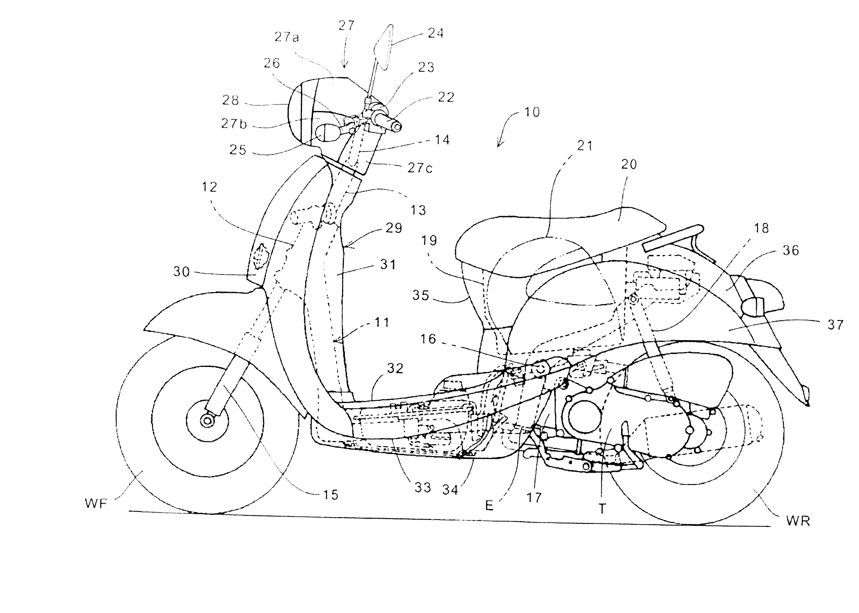
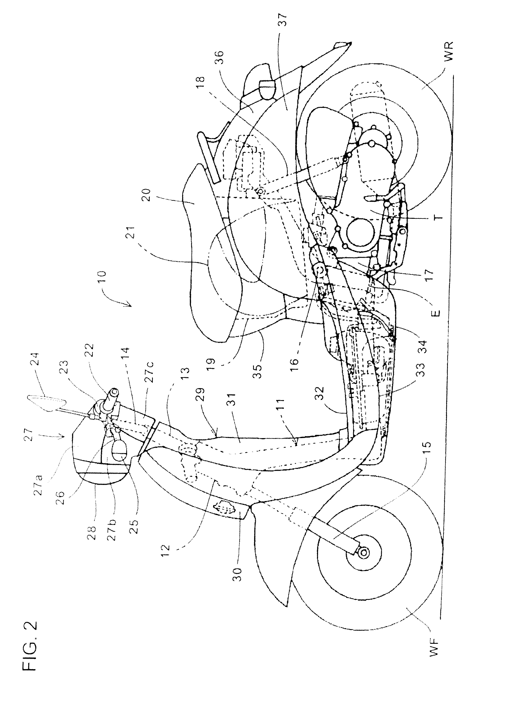
[0043]Embodiments of the present invention will be explained hereinafter with reference to the drawings. FIG. 1 is a front view of a motorcycle as a saddle-ride type vehicle provided with a turn signal device according to an embodiment of the present invention. FIG. 2 is a side view of the same. The motorcycle 10, in this example, is a scooter-type vehicle includes a steering axis 13 that vertically penetrates a head pipe 12 constituting a front section of a vehicle body frame 11 and is rotatably supported by the head pipe. A handlebar 14 and a front fork 15 branching to the left and right of a vehicle body are jointed to an upper portion and a lower portion of the steering axis 13, respectively. A front wheel WF is rotatably supported on a lower end of the front fork 15.

[0044]A power unit 17 which includes an engine such as a water-cooled type four cycle engine E and a centrifugal clutch-attached belt-type continuously variable transmission T is vertically swingably coupled to a re...


PUM


Abstract

A saddle-ride type vehicle has a handlebar cover 27 covering at least a front portion of a handlebar 14. The vehicle includes a turn signal device having mounting stays 26 jointed to the handlebar bar 14, and lamp members 25 supported on the mounting stays 26. The handlebar cover 27 covering the front portion of the handlebar 14 has opening portions 47 formed so as to face in a vehicle body forward direction. The mounting stays 26 penetrate the opening portions 47 and extend in the vehicle body forward direction from the handlebar 14. The lamp members 25 are connected to front end portions of the mounting stays 26. The mounting stays 26 are jointed to end portions 14c of the handlebar 14. Stay covers 45 which cover the mounting stays 26 can be provided.

Description

BACKGROUND [0001]1. Field[0002]Embodiments of this invention relate to a turn signal device of a saddle-ride type vehicle which is attached to a handlebar and, more particularly, to a turn signal device of a saddle-ride type device which is suitable for enhancing visibility and functionality.[0003]2. Description of the Related Art[0004]Regarding a turn signal device that is provided at a saddle-ride type vehicle (typically, a motorcycle), various attaching structures have been used. For example, a turn signal device described in Patent Literature 1 (JPU No. S62-176902) has a structure in which turn signals or winker lamps (lamp members) are attached to tip ends of support arms which are extended outward in a vehicle body width direction relative to lamp mounting stays that are fixed to a handlebar.[0005]In the meantime, when attention is given to a design of the turn signal device attached to the handlebar as described in the Patent Literature 1, the mounting stays and the support a...

Claims


Application Information

Patent Timeline
IPC IPC(8): B62K21/12B60Q1/38
CPCB60Q1/2657B60Q1/38B62J6/005Y10T74/20822B62K11/14B62K2202/00B62J17/02B62J6/056
Inventor TAJIMA, KATSUKISUMADA, TAKASHIHAYASHI, TOMONORISAKANE, TAIKI
Owner HONDA MOTOR CO LTD
Why Eureka
Try Eureka