
Method and apparatus for reducing and controlling highway congestion to save on fuel costs

a technology of highway congestion and fuel cost, applied in the direction of roads, instruments, traffic signals, etc., can solve the problems of drivers not being able to see disturbance, reduce the reward of rubbernecking, reduce the waste of fuel waiting in long traffic lines, and reduce the flow of congested traffic

Inactive Publication Date: 2011-07-07
TRACKTHINGS
View PDF31 Cites 1 Cited by
  • Summary
  • Abstract
  • Description
  • Claims
  • Application Information

AI Technical Summary

Benefits of technology

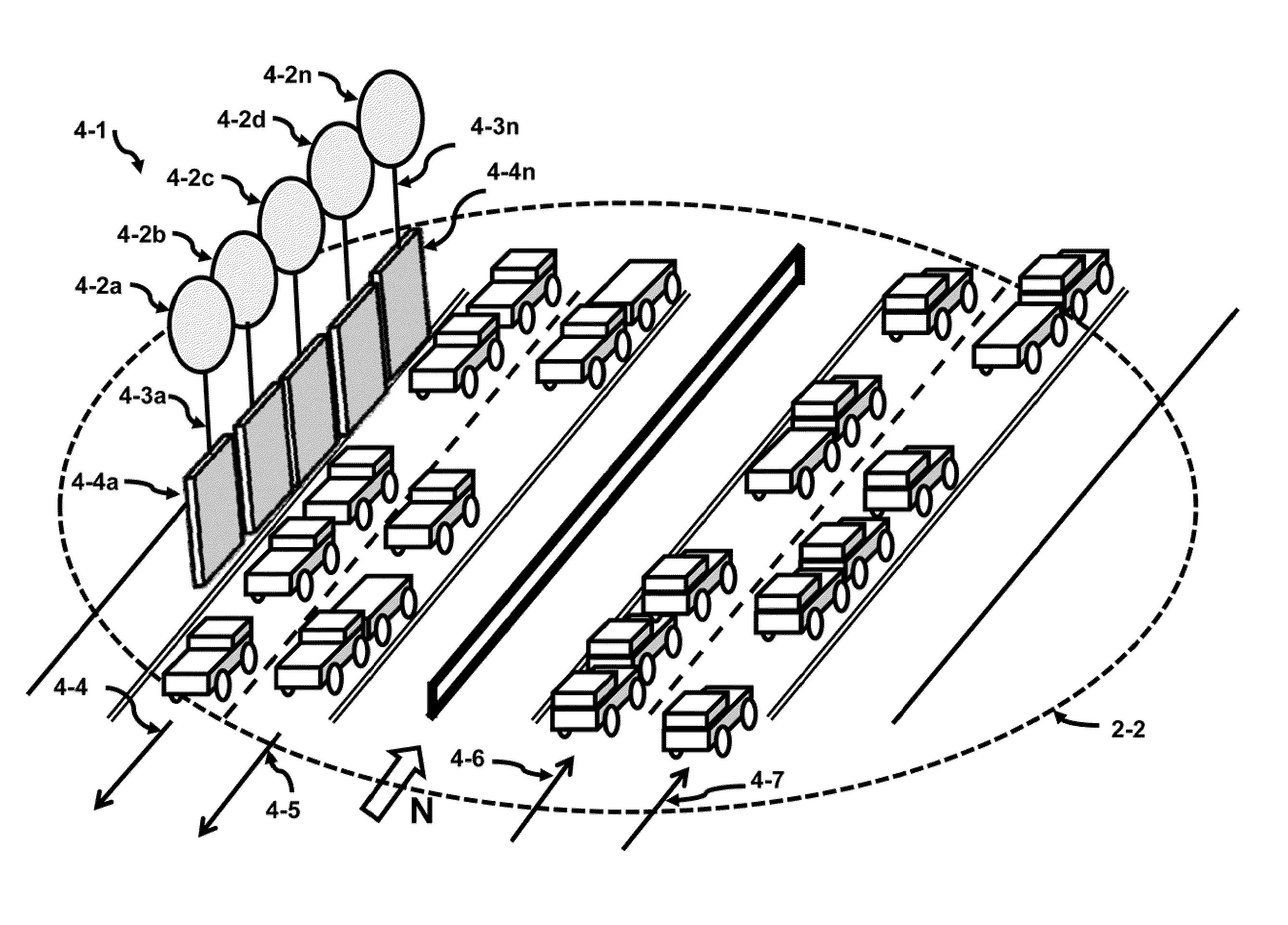
[0007]The second view is a quickly erected shield that blocks the view of the disturbance from the passing drivers. This shield could have standardized appearance, but the net result will be that the driver would not be able to see disturbance. Features such as color, width and height of the shield or shields can be resolved to provide for better uniformity of the second view. As the uniformity improves, there will be a lesser chance for the driver or motorist to slow down.
[0009]Another aspect of this invention is to control the flow of congested traffic in real time. Wirelessly controlled mobile flat units can be placed on the shoulder of the road and then moved onto the roadway remotely controlled by a master unit. As these flat units are moved onto the roadway, the congested traffic can run over these flat units without damaging them. Once these units are in position, a signal is given to raise or extend a reflective, illuminated post which also has an LCD (Liquid Crystal Display) display. This spacing of these marked posts defines and establishes a new dynamically adjusted roadway. As the traffic follows these roadways, the congestion becomes reduced until it is eliminated.
[0011]Another aspect of this invention is that the marked posts are positioned with the guidance of a master processor that has the details of the roadway in memory. The memory can be in the master processor or located on a web server. If the master processor knows; 1) which roadway is blocked, 2) the location of the accident, and 3) the positioning of the mobile flat units, the master processor issues instructions to the mobile units to optimize and reduce the flow of the congested traffic.
[0012]Once the shields are in place and the reward of rubbernecking is reduced, the traffic will become less affected by the rubbernecking event and the waste of fuel waiting in long traffic lines can be decreased. In addition, because of the active control of congested traffic, the ability to control and reduce congestion offers another approach to improving fuel usage in the US.

Problems solved by technology

This shield could have standardized appearance, but the net result will be that the driver would not be able to see disturbance.

Method used


Image

  • Method and apparatus for reducing and controlling highway congestion to save on fuel costs
  • Method and apparatus for reducing and controlling highway congestion to save on fuel costs
  • Method and apparatus for reducing and controlling highway congestion to save on fuel costs

Examples


Embodiment Construction

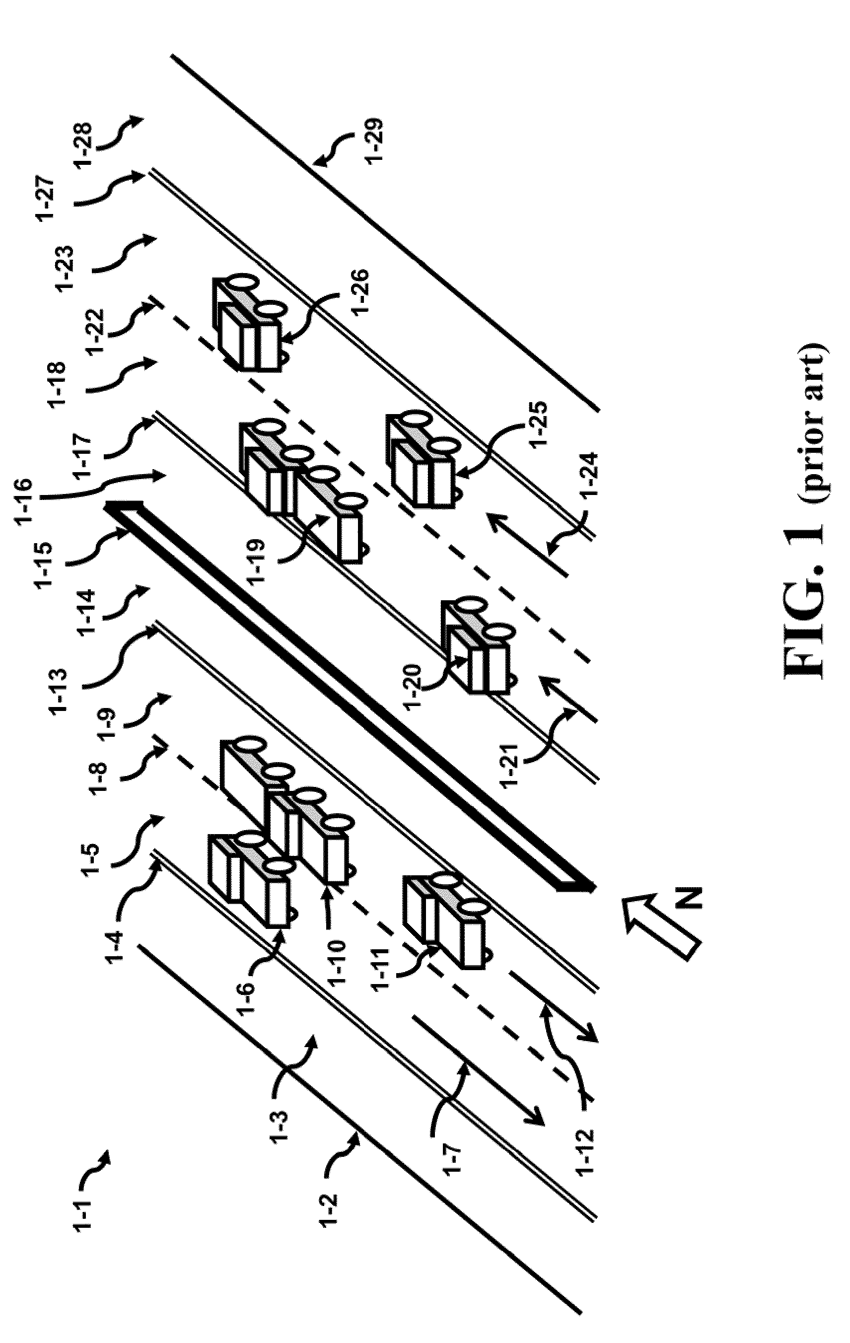
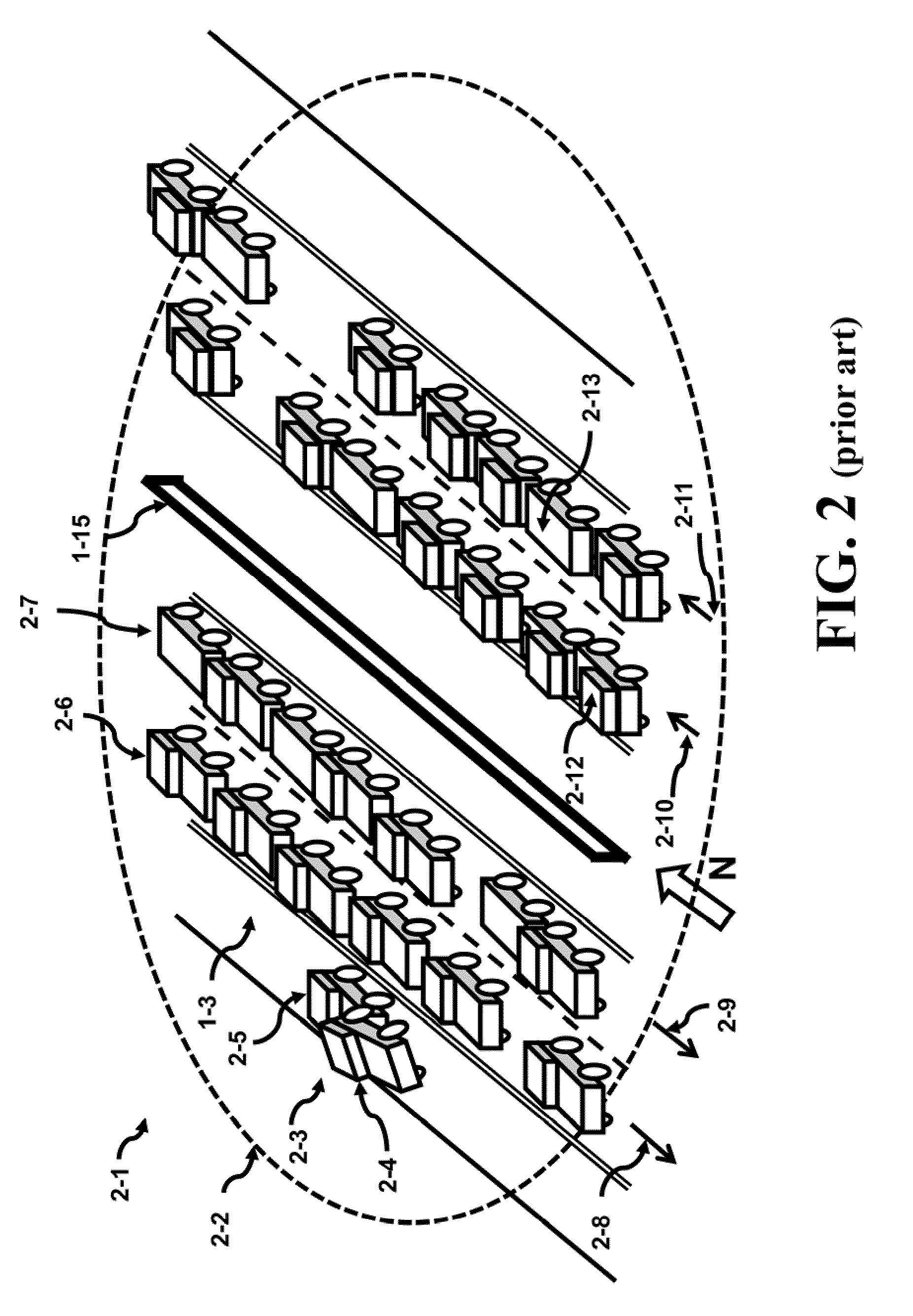
[0035]FIG. 1 illustrates a view of a typical highway or interstate 1-1. The highway is bounded by 1-2 and 1-29 which defines the paved region of the highway. This highway 1-1 stretches from North to South as shown by the arrow. The highway has four paved lanes 1-16, 1-18, 1-23 and 1-28 heading North and has four paved lanes 1-3, 1-5, 1-9 and 1-14 heading South. The North and South directions are separated by the concrete barrier 1-15. Each of the two outer lanes of the North and South directions serve as shoulders. The inner shoulders of the North and South directions are 1-16 and 1-14, respectively. The outer shoulders the North and South directions are 1-28 and 1-3, respectively. The active portion of the highway comprises lanes 1-18 and 1-23 traveling North and the lanes 1-5 and 1-9 traveling South.

[0036]The various lanes are separated by barriers, markings, depressions, or lines for demarcation purposes. For instance, the lanes that are traveling South 1-3, 1-5, 1-9 and 1-14 are...


PUM


Abstract

One estimate indicates that rubbernecking and congestion consumes about 4% of this country's fuel. Two approaches are presented to help solve this problem. The first uses shields to block the view of a car accident. Rubbernecking is reduced since the visibility of the car accident is reduced. A second approach uses mobile flat units that can be remotely controlled to enter a roadway that is carrying active traffic. The traffic runs over these units that are being moved until the master processor indicates that the mobile flat units are in position. A post is extended from the flat unit that issues commands to the motorists so the master processor can begin to control and reduce congestion. Both approaches can be used to help decrease fuel waste in the US.

Description

BACKGROUND OF THE INVENTION[0001]When congestion or rubbernecking occurs on major highways, vehicles stand still and idle their engines. As the congestion builds up, the wait time increases. The congestion wastes fuel and aggravates the driver's nerves.[0002]Often it is the drivers own curiosity that helps to fuel the delay which is known as rubbernecking. As the name implies, rubbernecking refers to the action of passing drivers or motorists who divert their attention from the roadway in front of them to the unusual situation that is existing within eyeshot of the driver. This unusual situation can be a car accident, a hit pedestrian, road construction, road repair, a patrol car that pulled over a motorist, or some other disturbance. Because the driver is drawn to the disturbance, the driver must slow the car down to get a better view, and this leads to what is known as “rubbernecking.”[0003]It is a desire of this invention to address several issues regarding rubbernecking; 1) find...

Claims


Application Information

Patent Timeline
Patent Type & Authority Applications(United States)
IPC IPC(8): B60Q7/00E04H17/00G05B15/02
CPCE01F9/00E01F7/00E01F9/617E01F9/646E01F9/688
Inventor GABARA, CASSANDRAGABARA, THADDEUS
Owner TRACKTHINGS
Learn More