Eureka AIR delivers breakthrough ideas for toughest innovation challenges, trusted by R&D personnel around the world.

Inductive charger and charging method

a charging method and charger technology, applied in the direction of electric variable regulation, process and machine control, instruments, etc., can solve the problems of inefficiency of 0057581-a1, system us-2007, and inability to be considered by a skilled man, so as to increase the efficiency of magnetic coupling

Active Publication Date: 2011-07-07
KONINKLIJKE PHILIPS ELECTRONICS NV
View PDF9 Cites 54 Cited by
  • Summary
  • Abstract
  • Description
  • Claims
  • Application Information

AI Technical Summary

Benefits of technology

[0017]In view of the above, there is a need for a universal inductive charger, wherein a single primary unit can supply power to different secondary devices thereby eliminating the need for a collection of different adaptors and chargers, having an increased magnetic coupling efficiency.SUMMARY OF THE INVENTION
[0021]The inductive charger of the invention has the following features. It is universal, i.e. a single charger can supply power to different appliances with different power requirements thereby eliminating the need for a collection of different adaptors and chargers. It is convenient, as the charger allows the appliances to be placed anywhere within the circular pattern of primary coils, thereby eliminating the need for plugging-in or placing the appliances accurately relative to the charger. The charger can supply power to a number of appliances with different power requirements at the same time. The charger offers flexibility for use in different environments, as no direct electrical contact is required thereby allowing use in wet, gaseous, clean and other atypical environments.
[0024]In an embodiment, each primary coil pair is provided with one or more switches for short circuiting the respective primary coil pair. Optionally, the charger comprises a processor for driving the AC power source, wherein the processor is adapted to short circuit at least one of the primary coil pairs using the corresponding switches, and to provide the supply the alternating current to the remaining primary coil pairs. Short circuiting some of the primary coil pairs provides a more homogeneous magnetic field. The efficiency and magnetic coupling are increased, thus limiting energy loss. The magnetic coupling can increase for instance up to three times compared to a charger lacking the appropriate circuitry.
[0025]In an embodiment, the charger comprises a cover of high magnetic permeability material that encloses the outside of the primary coils. Although electromagnetic radiation of the above-described charger is within regulatory limits, the cover can lower electromagnetic radiation down to a predetermined level, thus enabling lower electromagnetic emissions outside the charger.

Problems solved by technology

Although interesting, the system of US-2007 / 0057581-A1 would be disregarded by a skilled man due to lack of detail and practicality.
In practice the system of US-2007 / 0057581-A1 will be more inefficient than any of the systems for contact-less energy transfer disclosed in the introduction, for instance due to the power needed to cool the superconducting magnets.

Method used


Image

  • Inductive charger and charging method
  • Inductive charger and charging method
  • Inductive charger and charging method

Examples


Embodiment Construction

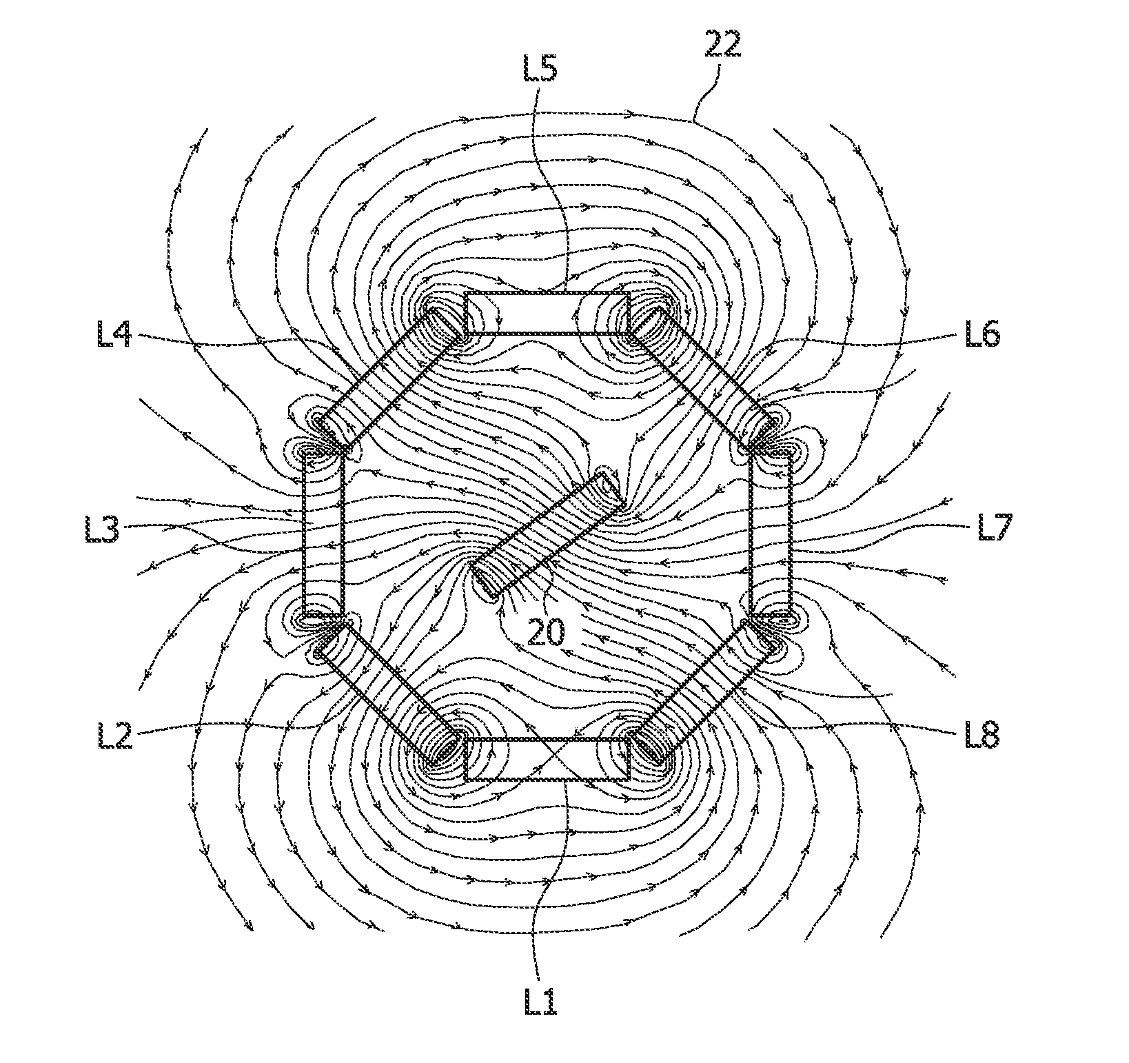
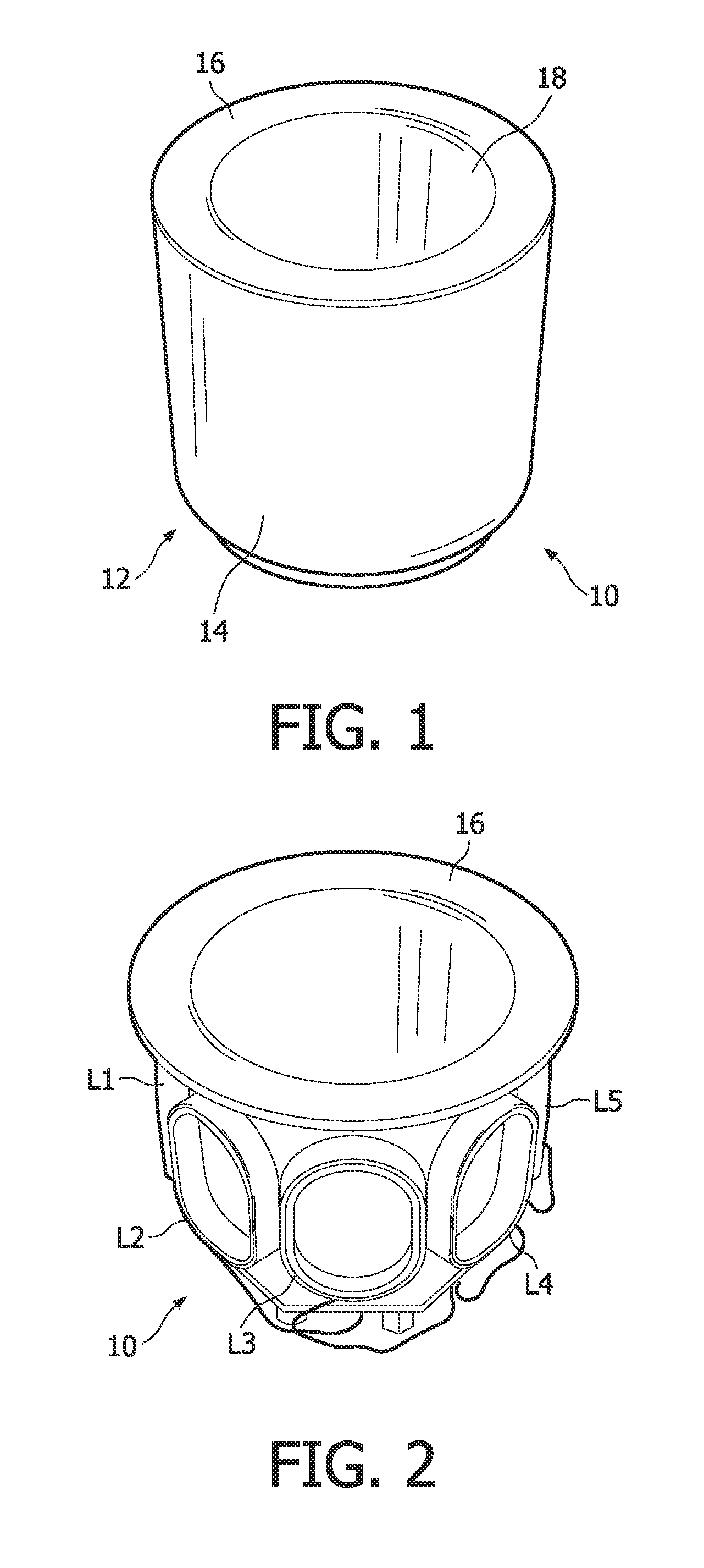
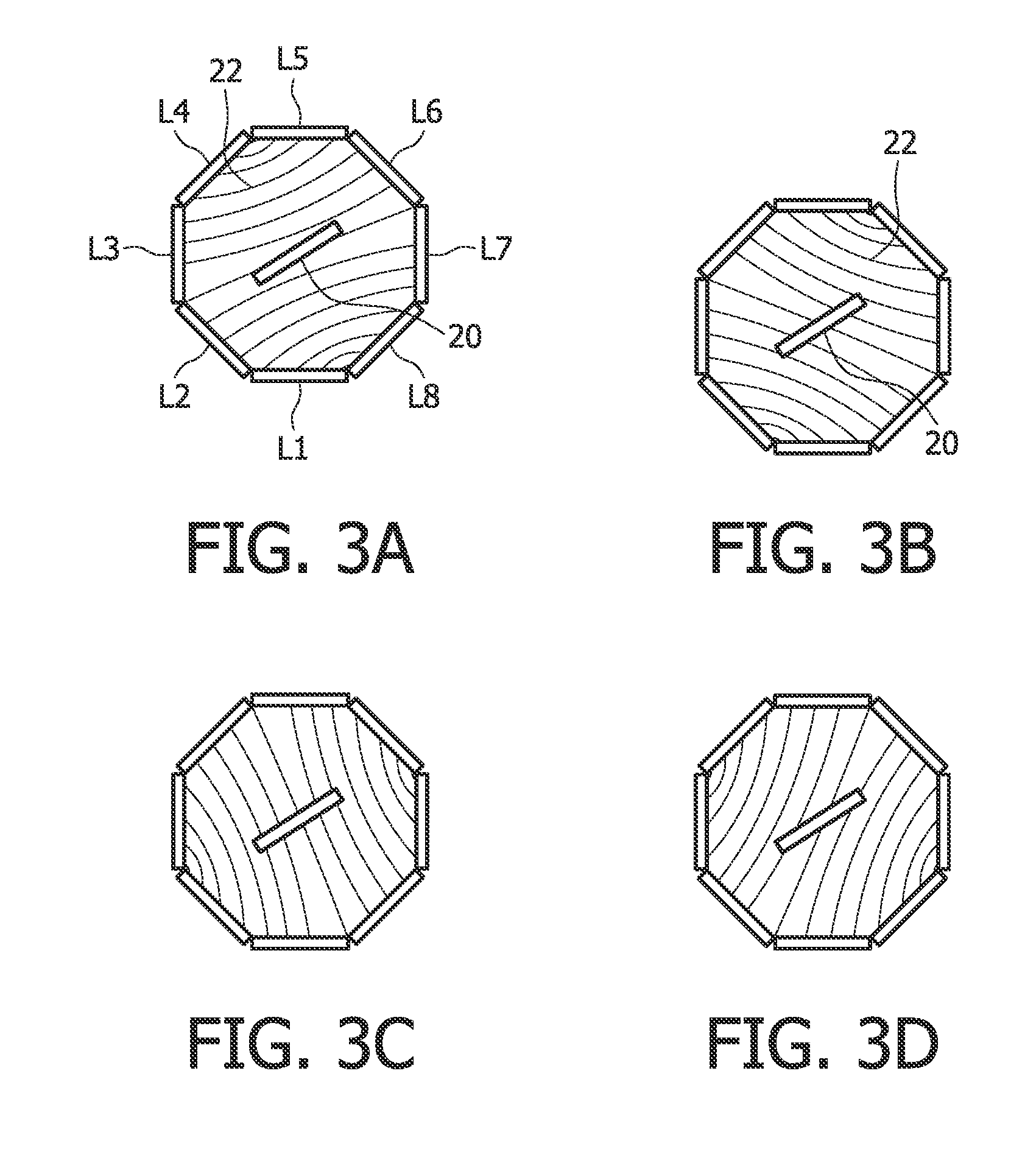
[0045]A contactless, inductive charger 10 according to the invention comprises a container 12. The container is for instance a cup including an outer cup-shaped member 14 and an inner cup-shaped member 16. A number of primary coils is arranged in a circular pattern along the circumference and in between the walls of the cup-shaped members 14 and 16. The primary coils are arranged in pairs, wherein each primary coil pair includes two opposing coils. I.e., a first pair includes coils L1 and L5, a second pair includes coils L2 and L6, etc. The embodiment of FIG. 1 comprises eight coils L1 to L8, and four coil pairs. Cup-shaped member 16 defines on its inside a space 18 wherein one or more battery powered appliances can be arranged for charging.

[0046]Each primary coil is a wire coil, without a core of magnetic material. Otherwise, the core would counteract the AC drive current due to the remanence of the magnetic material.

[0047]For inductively transferring power, an appliance comprising...


PUM


Abstract

The present invention provides a charger for inductively charging one or more battery powered appliances simultaneously. The charger comprises an external unit adapted to inductively provide power to the battery powered appliances, the external unit comprising: two or more primary coil pairs that are arranged in a circular pattern; an AC power source for providing an alternating current (AC) to the primary coil pairs for generating a rotating magnetic field between respective primary coils of the primary coil pairs; and a processor for driving the AC power source, wherein the one or more battery powered appliances are adapted to be arranged inside the circular pattern of the external unit, each appliance comprising a secondary coil for enclosing part of the magnetic field and in response generating a current for charging the battery of the appliance.

Description

FIELD OF THE INVENTION[0001]The present invention relates to an inductive charger and charging method. The charger is applicable for simultaneously charging one or more battery powered appliances using contact-less inductive coupling between the charger and the appliances.BACKGROUND OF THE INVENTION[0002]Many of today's portable appliances incorporate rechargeable batteries. Example appliances include electrical toothbrushes, electric shavers, beard trimmers, and / or depilation devices. The appliances may include other chargeable appliances also, such as cellular telephones or laptop computers.[0003]In some of these devices, the batteries are recharged via inductive coupling rather than a direct electrical connection. Examples include the Philips Sonicare™ toothbrush, the Panasonic Digital Cordless Phone Solution KX-PH15AL and the Panasonic men's shavers ES70 / 40 series.[0004]Each of these devices typically has an adaptor or charger which takes power from mains electricity, a car ciga...

Claims


Application Information

Patent Timeline
Patent Type & Authority Applications(United States)
IPC IPC(8): H02J7/00
CPCH02J7/025H02J7/0013H02J50/402H02J7/0044H02J50/12H01F38/14H02J50/40H02J50/50G05F3/06H04B5/79
Inventor ETTES, WILHELMUSVISSER, ROBERT PAULVAN DER LINDEN, JACOB ADRIANUS
Owner KONINKLIJKE PHILIPS ELECTRONICS NV
Why Eureka
Eureka Blog
Learn More