
Aluminum Alloy Vacuum Casting Equipment

a vacuum casting and aluminum alloy technology, applied in the field of aluminum alloy production equipment and aluminum alloy vacuum casting equipment, can solve the problems of not being able to obtain tips from current reported methods and equipments, not being able to meet the requirements of manual operations, and only reaching about 30% of qualified rate, so as to reduce production costs, reduce labor greatly, and eliminate various risk factors

Active Publication Date: 2011-07-07
JINAN CASTING FORGING MACHINERY INST
View PDF4 Cites 1 Cited by
  • Summary
  • Abstract
  • Description
  • Claims
  • Application Information

AI Technical Summary

Benefits of technology

The invention is an aluminum alloy vacuum casting equipment that automates the casting process to reduce labor, eliminate dangerous factors, and improve efficiency. The equipment includes a high-pressure reactor tank with guides and connected to a compressed air pipe and booster jar. There are also first and second casting windows with associated piston rods and cylinders. The reactor tank has a moonpool door and two guides connected to pivots and cylinders. The equipment is designed to realize casting in vacuum, improve safety, and reduce production costs. It also allows for heat treatment and production of aluminum-magnesium alloy castings.

Problems solved by technology

Disadvantages of this equipment: Manual operations are necessary due to improper structure, hard and dangerous, high waste castings, especially for casting of large thin parts, there are much pinholes and secondary slag entrapments on the castings, and the qualified rate only reaches about 30%.
And no tips can be obtained from current reported methods and equipments.

Method used


Image

  • Aluminum Alloy Vacuum Casting Equipment
  • Aluminum Alloy Vacuum Casting Equipment
  • Aluminum Alloy Vacuum Casting Equipment

Examples


Embodiment Construction

[0011]This invention is described additionally combining the figures and example of implementation.

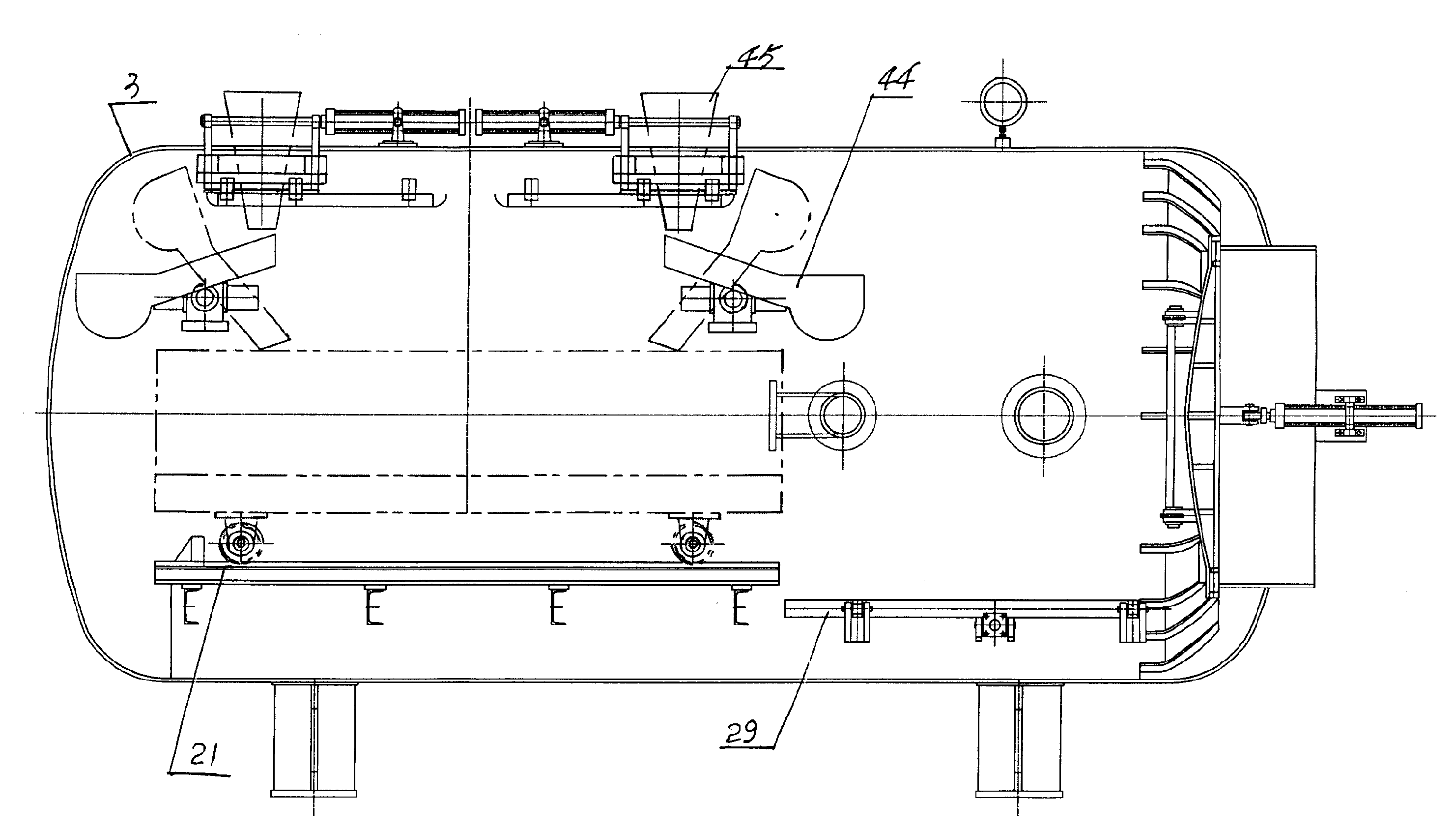
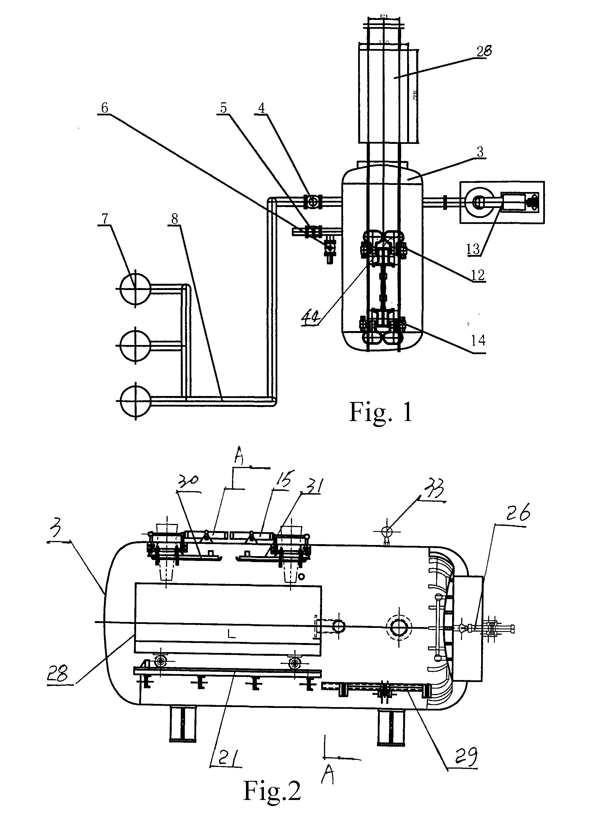
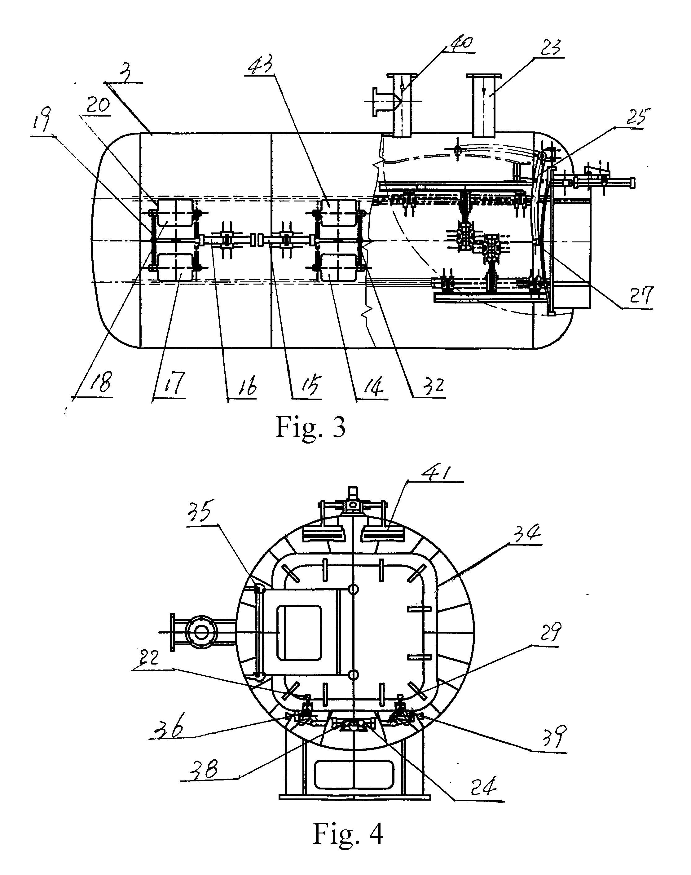
[0012]The High Pressure Reactor Tank is shown in FIG. 3. The High Pressure Reactor Tank 3 is equipped with guide inside. The High-pressure Reactor Tank (3) is connected with one end of the Compressed Air Pipe (8). The other end of Compressed Air Pipe (8) is connected with Booster Jar (7). The Compressed Air Pipe (8) is equipped with air inlet Actuated Ball Valve (4). First Casting Window (17), Second Casting Window (18), Third casting window (14) and Fourth casting window (43) are sets at top of the High-pressure Reactor Tank (3). The First Casting Window (17) and Second Casting Window (18) are equipped with First Cylinder (16) at one side. The piston rod of First Cylinder (16) is connected with First Connecting-rod (19). The First Connecting-rod (19) is connected with the casting window cover (20). The Third Casting Window (14) and Fourth Casting Window (43) are equipped with Second C...


PUM

PropertyMeasurementUnit
pressureaaaaaaaaaa
Pressureaaaaaaaaaa
lifetimeaaaaaaaaaa

Abstract

An aluminum alloy vacuum casting equipment is studied in this invention, including High Pressure Reactor Tank. The High Pressure Reactor Tank is equipped with guide inside. The High-pressure Reactor Tank is connected with one end of the Compressed Air Pipe. The other end of Compressed Air Pipe is connected with Booster Jar. First Casting Window and Second Casting Window are sets at top of the High-pressure Reactor Tank. The First Casting Window and Second Casting Window are equipped with First Cylinder at one side. The piston rod of First Cylinder is connected with First Connecting-rod. The First Connecting-rod is connected with the casting window cover. The High Pressure Reactor Tank is equipped with Fixed Guide and Unfixed Guide at the bottom. The High Pressure Reactor Tank is equipped with Moonpool Door. The other end of Door Connecting-rod is connected with High Pressure Reactor Tank. The Moonpool Door is connected with Third Cylinder. The High Pressure Reactor Tank is equipped with Actuated Exhaust Ball Valve at one side. Advantages of this invention: All procedures except for putting / fetch of the filler are fulfilled automated, realizing casting in vacuum, reducing labor greatly, providing a safe and reliable equipment for casting of large thin parts.

Description

FIELD OF THE INVENTION[0001]This invention concerns aluminum alloy production equipment, aluminum alloy vacuum casting equipment used for casting in vacuum.BACKGROUND OF THE INVENTION[0002]Casting of aluminum alloy working pieces are mainly finished in the tank body. For casting of working pieces using High Pressure Reactor Tank body, the sand-box is lifted onto the trolley. Lay the Unfixed Guide in the High Pressure Reactor Tank down, and open the door manually. Then erect the Unfixed Guide. Push the sand-box trolley into the tank body and position manually at last. Then the casting positioning, casting, boosting, solidifying, exhaust and output of sand-box are all finished manually. Disadvantages of this equipment: Manual operations are necessary due to improper structure, hard and dangerous, high waste castings, especially for casting of large thin parts, there are much pinholes and secondary slag entrapments on the castings, and the qualified rate only reaches about 30%. So, How...

Claims


Application Information

Patent Timeline
Patent Type & Authority Applications(United States)
IPC IPC(8): B22D18/06
CPCB22D27/15
Inventor KANG, JINGLE
Owner JINAN CASTING FORGING MACHINERY INST
Learn More