
Memory device wear-leveling techniques

a technology of memory devices and wear levels, applied in the field of memory device wear leveling techniques, can solve the problems of/or the electronic device containing flash memory, affecting the performance of flash memory, and halting operation

Inactive Publication Date: 2011-06-30
NVIDIA CORP
View PDF47 Cites 25 Cited by
  • Summary
  • Abstract
  • Description
  • Claims
  • Application Information

AI Technical Summary

Benefits of technology

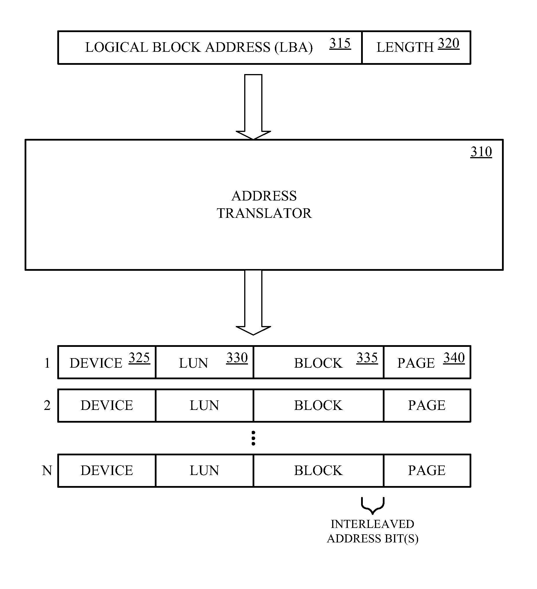
[0003]Embodiments of the present technology are directed toward memory device wear-leveling techniques. In one embodiment, a wear-level method includes translating a logical block address and a length in the logical block address that specifies a number of logical pages, to a plurality of physical addresses for accessing one or more memory devices. Each physical address includes a device address, a logical unit address, a block address, and a page address.
[0004]In another embodiment, a wear-leveling memory controller discovers a persistent state of one or more memory devices. The memory controller also builds and caches persistent state parameters for each logical unit of a given memory device if a persistent state is not discovered for the given memory device.

Problems solved by technology

Such memory devices can sustain a limited number of erase cycles during their operational lifespan.
When the endurance of the flash memory is exceeded, the performance of the flash memory and / or the electronic device containing the flash memory may be adversely impacted, or it may even stop operating.

Method used


Image

  • Memory device wear-leveling techniques
  • Memory device wear-leveling techniques
  • Memory device wear-leveling techniques

Examples


Embodiment Construction

[0010]Reference will now be made in detail to the embodiments of the present technology, examples of which are illustrated in the accompanying drawings. While the present technology will be described in conjunction with these embodiments, it will be understood that they are not intended to limit the invention to these embodiments. On the contrary, the invention is intended to cover alternatives, modifications and equivalents, which may be included within the scope of the invention as defined by the appended claims. Furthermore, in the following detailed description of the present technology, numerous specific details are set forth in order to provide a thorough understanding of the present technology. However, it is understood that the present technology may be practiced without these specific details. In other instances, well-known methods, procedures, components, and circuits have not been described in detail as not to unnecessarily obscure aspects of the present technology.

[0011]...


PUM


Abstract

The wear-leveling techniques include discovering a persistent state of one or more memory devices, or building and caching persistent state parameters for each logical unit of a given memory device if a persistent state is not discovered for a given memory device. The techniques may also include processing memory access commands utilizing the cached persistent state parameters. When processing memory access commands, the logical block address and length parameter of a logical address of a command may be translated to a plurality of physical addresses for accessing one or more memory devices, each physical address includes a device address, a logical unit address, a block address, and a page address, wherein the block address includes one or more interleaved address bits.

Description

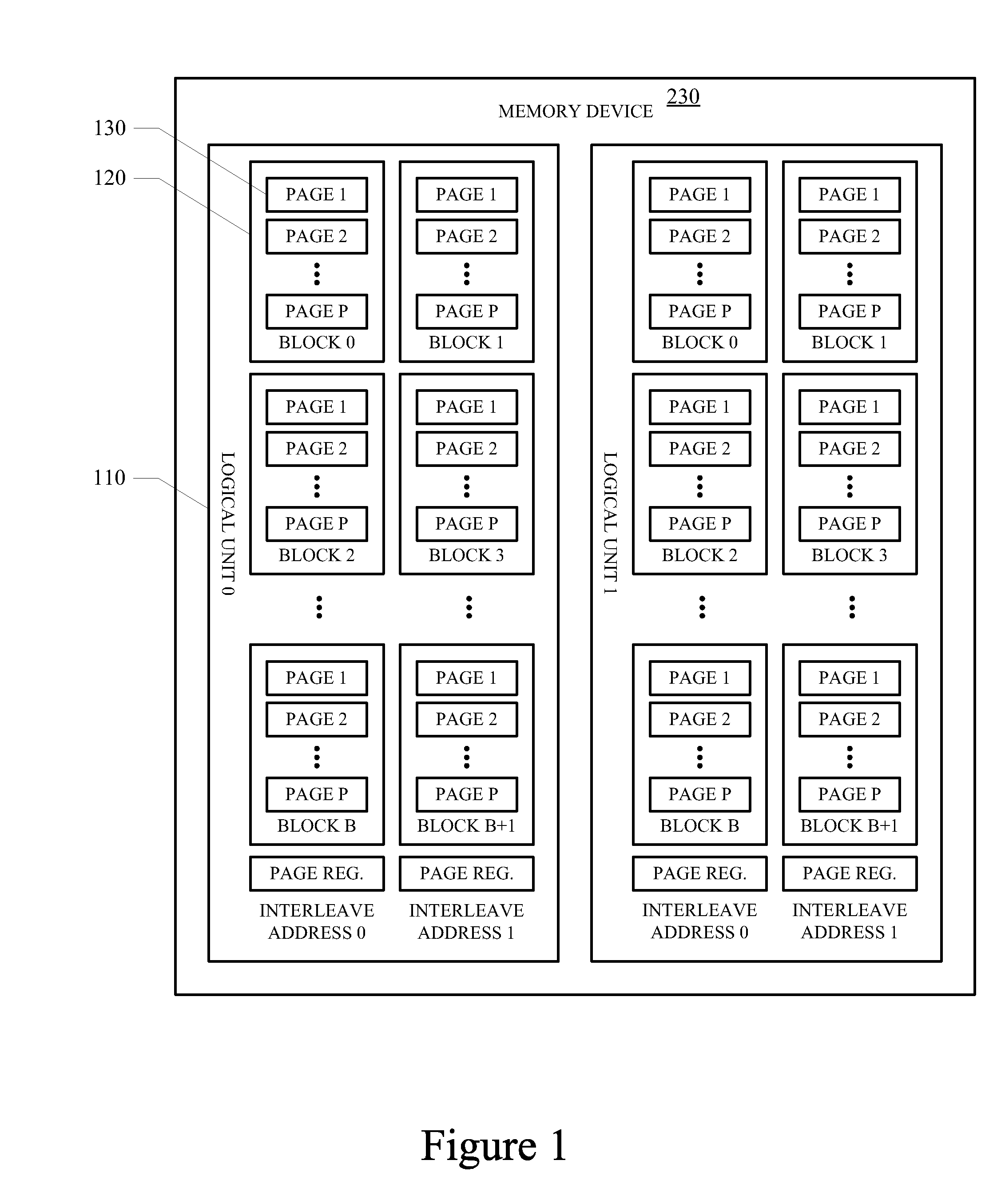
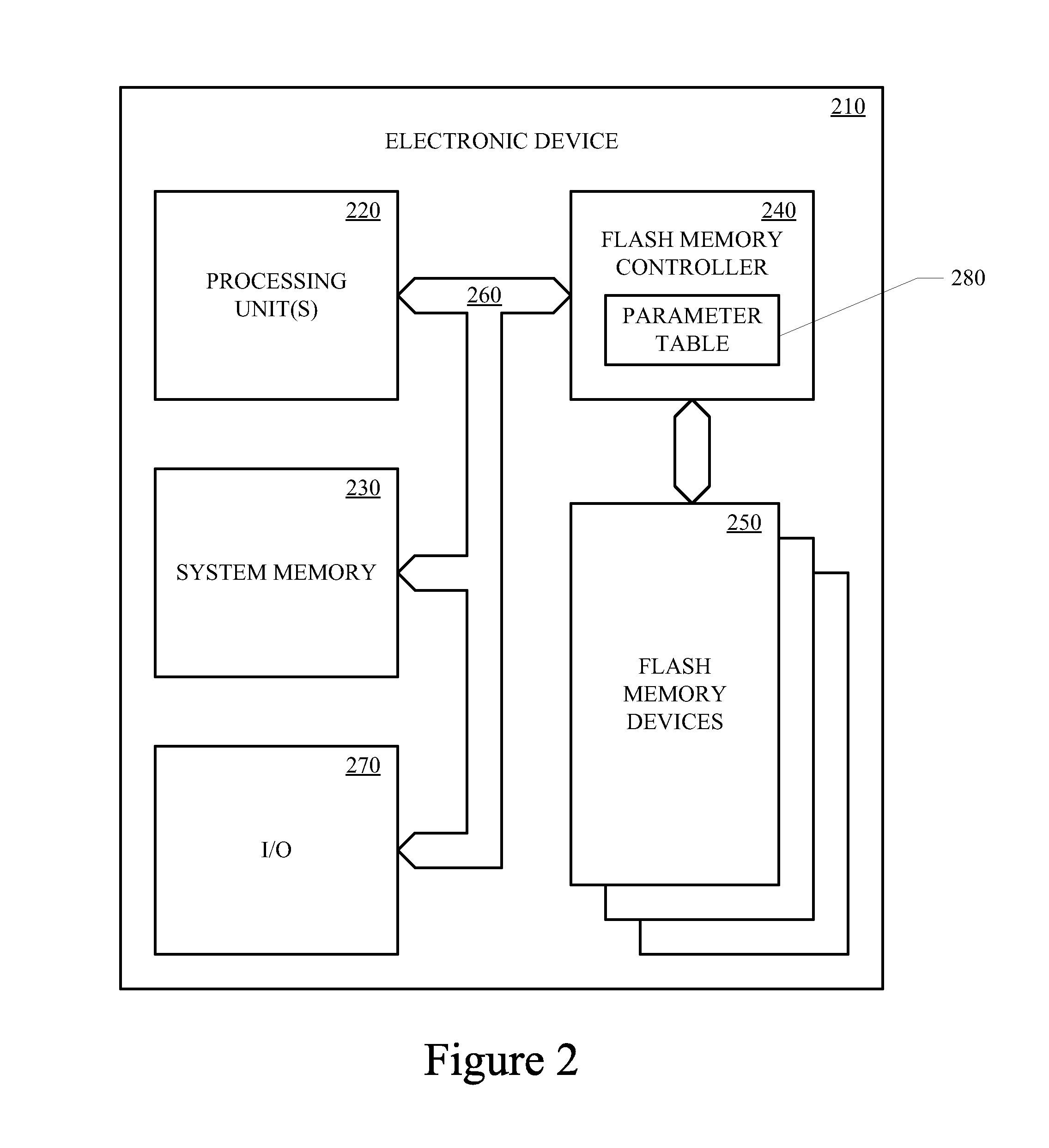
BACKGROUND OF THE INVENTION[0001]Various types of memories are designed to be erased and programmed in large sections, and are generally referred to as flash memory. Such memory devices can sustain a limited number of erase cycles during their operational lifespan. The number of erase cycles that a flash memory can sustain and continue to reliably operate may be expressed as the endurance of the memory device. Generally, a given memory cell of a flash memory device can currently be erased between 10,000 and 100,000 times before it fails to reliably operate. The endurance of a memory device may depend on the semiconductor processes used to manufacture the device, and the architecture of the memory device.[0002]Flash memory is common in various conventional electronic devices. When the endurance of the flash memory is exceeded, the performance of the flash memory and / or the electronic device containing the flash memory may be adversely impacted, or it may even stop operating. Accordin...

Claims


Application Information

Patent Timeline
Patent Type & Authority Applications(United States)
IPC IPC(8): G06F12/06G06F12/00
CPCG06F12/0246G06F2212/7211G06F12/0607
Inventor SAXENA, NIRMALTSAI, HOWARDVYSHETSKY, DMITRYLIN, YEN
Owner NVIDIA CORP
Learn More