
Medical Affixation Device

a technology of affixing device and affixing device, which is applied in the field of affixing device, can solve the problems of long surgical recovery time, inability to provide the functionality of the damaged tissue permanently, and inability to fully discharge the operation, so as to prevent damage to the soft tissue incurred through in vivo affixing procedure, the effect of reducing the amount of damag

Inactive Publication Date: 2011-06-30
HENDREN RONALD D +1
View PDF31 Cites 26 Cited by
  • Summary
  • Abstract
  • Description
  • Claims
  • Application Information

AI Technical Summary

Benefits of technology

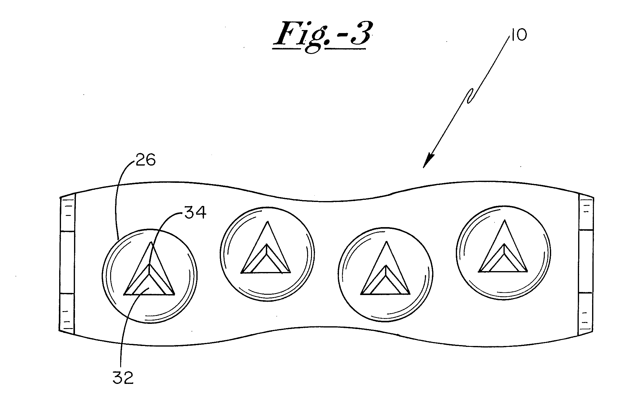
[0009]By means of the present invention, damage to soft tissue incurred through in vivo affixation procedures may be substantially reduced. To do so, the medical affixation device of the present invention focuses adherence impact at body tissue contact portions, which represent only a fraction of the total surface area of the main body portion of the affixation device. As a result, the remaining non-contacting portions either remain spaced from the damage-susceptible soft body tissue, or come into contact with such tissue at a force sufficiently low to prevent damage thereto.

Problems solved by technology

Such pressure upon the soft tissue tends to constrict or block altogether capillary vessels coursing through the soft tissue.
It has been found that such soft tissue damage can lengthen surgical recovery time and can require physical therapy to re-establish appropriate functionality originally provided by the damaged tissue.
In some cases, the functionality provided by the damaged tissue may be permanently lost.
Such a methodology, however, requires a relatively large bore diameter, and can lead to soft tissue damage, as described above.
Other methodologies currently employed to secure such tissue portions to one another are relatively time-consuming and complex.

Method used


Image

  • Medical Affixation Device
  • Medical Affixation Device
  • Medical Affixation Device

Examples


Embodiment Construction

[0026]The objects and advantages enumerated above together with other objects, features, and advances represented by the present invention will now be presented in terms of detailed embodiments described with reference to the attached drawing figures which are intended to be representative of various possible configurations of the invention. Other embodiments and aspects of the invention are recognized as being within the grasp of those having ordinary skill in the art.

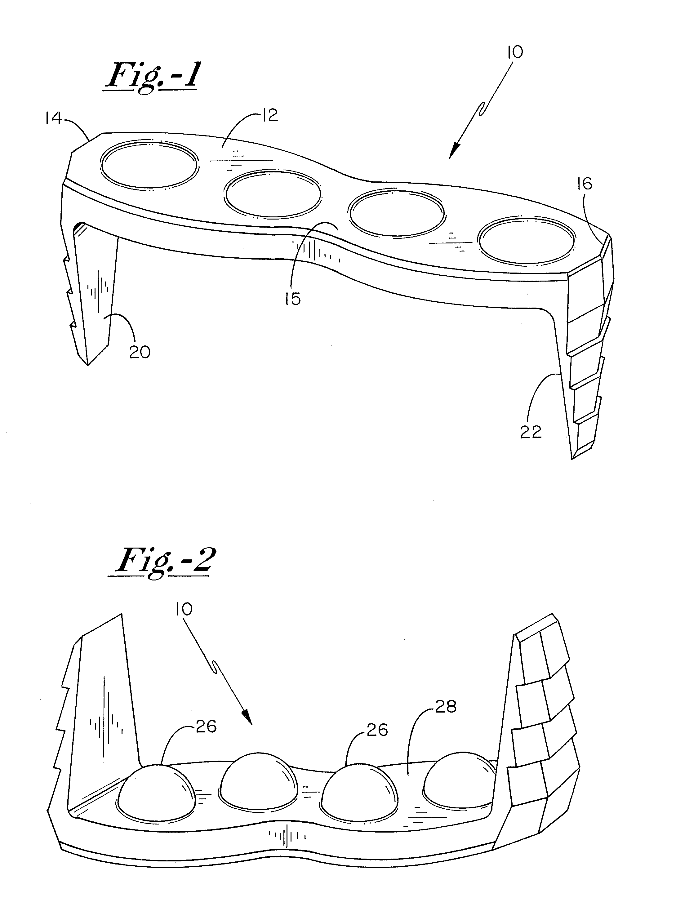
[0027]With reference now to the drawing figures, and first to FIG. 1, a medical affixation device 10 includes a main body portion 12 having first and second opposed ends 14, 16, from which first and second prongs 20, 22 extend. In preferred embodiments, affixation device 10 takes the form of a medical staple, although a variety of other configurations, such as medical plates, pins, and the like are contemplated as being within the scope of the present invention.

[0028]As illustrated in FIGS. 1 and 2, first surface 13 o...


PUM


Abstract

A medical affixation device for affixing a first body tissue portion to a second body tissue portion in vivo includes a main body portion having a first surface operably oriented in facing relationship with a first body tissue, wherein the first surface has a non-planar contour forming one or more body tissue contact portions and one or more non-contacting portion. The body tissue contact portions have an effective tissue contact surface area that is sufficiently large to prevent the body tissue contact portions from penetrating the first body tissue when the device is fully installed. The device further includes one or more prongs extending from the main body portion, and which are configured to penetrate the first body tissue upon installation of the device.

Description

CROSS REFERENCE TO RELATED APPLICATIONS[0001]This application is a divisional of U.S. patent application Ser. No. 11 / 265,613, entitled “Medical Affixation Device”, filed Nov. 2, 2005, the content of which being incorporated herein in its entirety.FIELD OF THE INVENTION[0002]The present invention relates to medical affixation devices generally, and more particularly to implantable devices such as medical staples and plates that minimize damage to soft tissue when utilized in vivo. In addition, the present invention relates to suture anchoring devices that provide an efficient platform to which tissue may be securely tethered.BACKGROUND OF THE INVENTION[0003]Medical affixation devices of various forms have long been used for stabilizing and / or securing body tissues in vivo. Common examples of such medical affixation devices include staples, plates, and pins that are manufactured from biocompatible materials so that such devices may be implanted within the body either temporarily or pe...

Claims


Application Information

Patent Timeline
IPC IPC(8): A61B17/04
CPCA61B17/0487A61B17/0642A61B17/0401A61B2017/0647A61B2017/0641
Inventor HENDREN, RONALD D.BECKER, DOUGLAS A.
Owner HENDREN RONALD D
Learn More