Eureka AIR delivers breakthrough ideas for toughest innovation challenges, trusted by R&D personnel around the world.

Dual-loop transmit noise cancellation

a transmit noise and dual-loop technology, applied in the field of communication systems, can solve the problems of increasing the cost of both approaches, affecting the detection of desired incoming signals, and affecting the accuracy of the signal, so as to remove estimated transmit noise and remove estimated transmit distortion

Active Publication Date: 2011-06-30
QUALCOMM INC
View PDF53 Cites 27 Cited by
  • Summary
  • Abstract
  • Description
  • Claims
  • Application Information

AI Technical Summary

Benefits of technology

The first filter may receive an output of the second mixer. The transmitter circuit may include a plant that receives an output of the third mixer and outputs the transmit signal. The plant may include an upconverter. The plant may include an amplifier. The first feedback loop may remove estimated transmit noise from the transmit signal. The second feedback loop may remove estimated transmit distortion from the transmit signal.
An output of the second filter may be the first input signal. The second feedback loop may include combining an output of the second filter with the second input signal to obtain a third combined signal. The third combined signal may be the first input signal. The first feedback loop may remove estimated transmit noise from the transmit signal. The second feedback loop may remove estimated transmit distortion from the transmit signal. The first input signal may include an inphase (I) modulated signal and a quadrature (Q) modulated signal. The second input signal may include an inphase (I) modulated signal and a quadrature (Q) modulated signal.

Problems solved by technology

In duplex systems, the noise generated by the transmitter that falls in the receiver's band is a significant problem.
Such noise makes it more difficult for the receiver to detect the desired incoming signal.
However, both approaches may be expensive.
A circuit solution may require high power consumption and / or larger devices.
Filters are generally large and costly and a separate filter is required for each frequency band of operation.

Method used


Image

  • Dual-loop transmit noise cancellation
  • Dual-loop transmit noise cancellation
  • Dual-loop transmit noise cancellation

Examples


Embodiment Construction

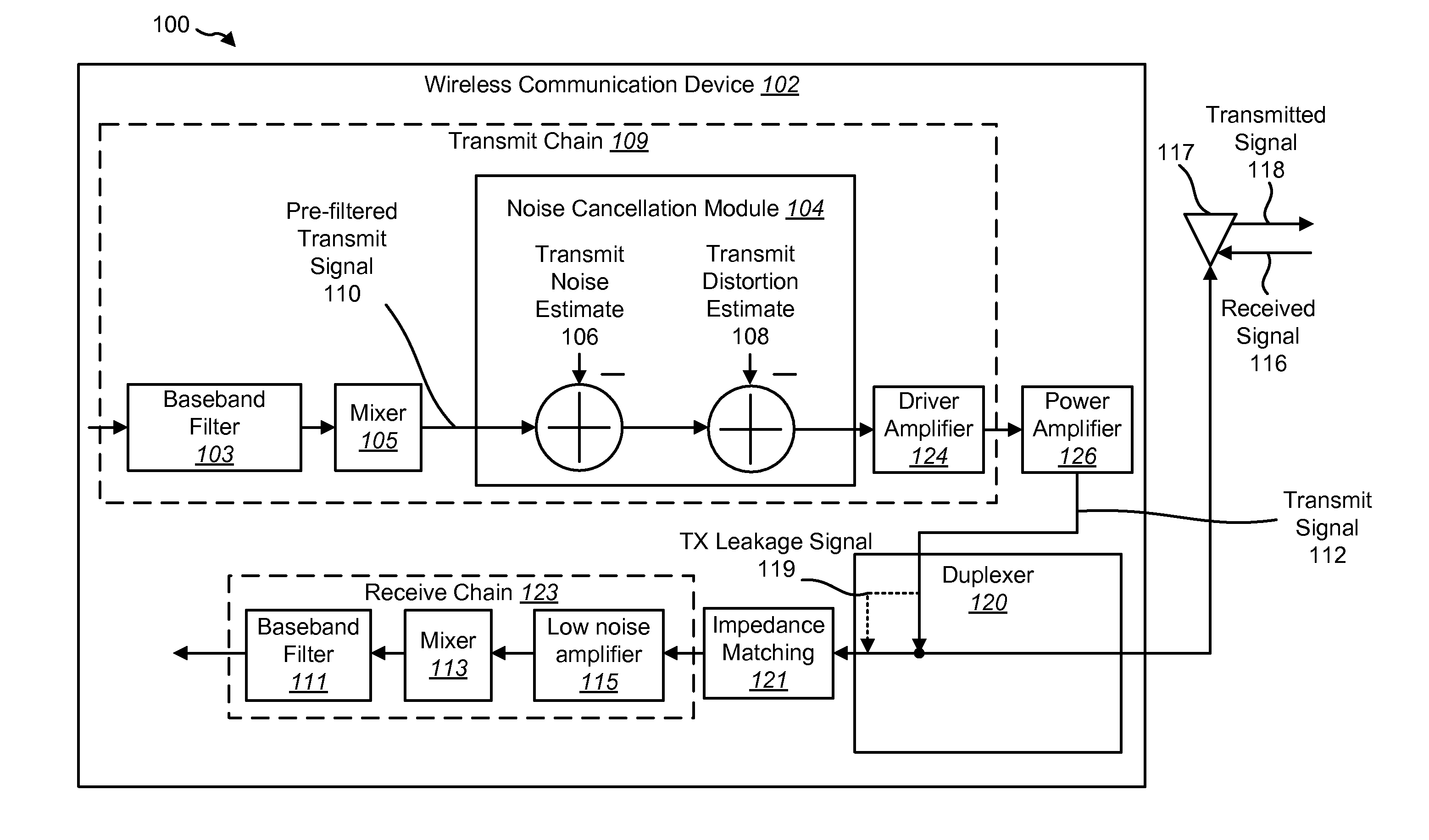
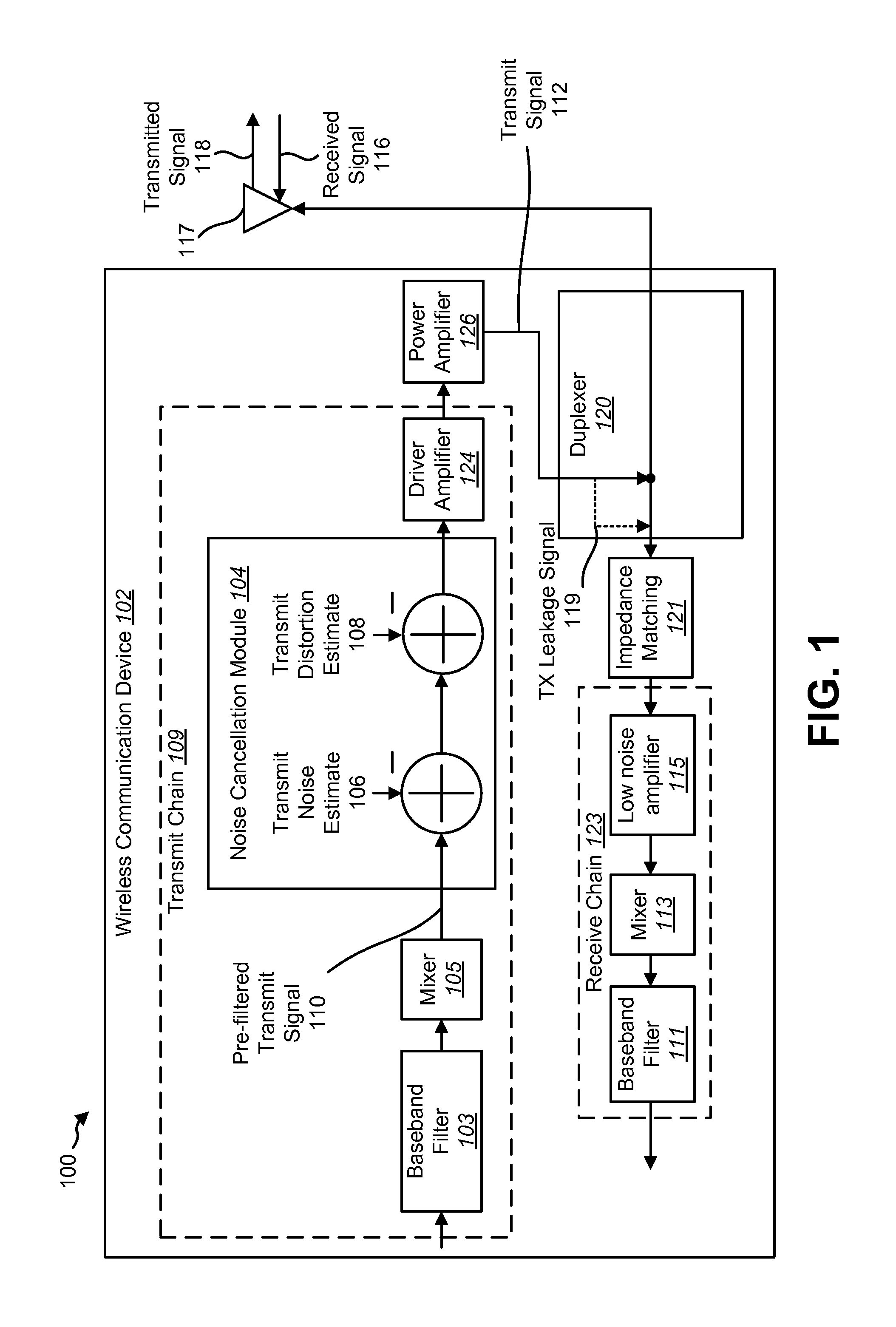
FIG. 1 shows a wireless communication system 100 with a wireless communication device 102. A wireless communication device 102 may be a base station, a mobile device, or the like. A base station is a station that communicates with one or more mobile devices. A base station may also be referred to as, and may include some or all of the functionality of, an access point, a broadcast transmitter, a Node B, an evolved Node B, etc. Each base station provides communication coverage for a particular geographic area. The term “cell” can refer to a base station and / or its coverage area depending on the context in which the term is used.

A mobile device may also be referred to as, and may include some or all of the functionality of, a terminal, an access terminal, a user equipment (UE), a subscriber unit, a station, etc. A mobile device may be a cellular phone, a personal digital assistant (PDA), a wireless device, a wireless modem, a handheld device, a laptop computer, etc. A mobile device ma...


PUM


Abstract

A transmitter circuit is described. The transmitter circuit includes a first local oscillator that generates a first frequency equal to a duplex frequency. The transmitter circuit also includes a second local oscillator that generates a second frequency equal to a receive frequency. The transmitter circuit further includes a first mixer that combines the first frequency with a first input signal. The transmitter circuit also includes a first feedback loop. The first feedback loop includes a second mixer that combines the second frequency with a transmit signal and a first filter and a first adder that combines an output of the first mixer with an output of the first filter. The transmitter circuit also includes a third local oscillator that generates a third frequency equal to the receive frequency. The transmitter circuit further includes a third mixer that combines the third frequency with an output of the first adder.

Description

TECHNICAL FIELDThe present disclosure relates generally to communication systems. More specifically, the present disclosure relates to systems and methods for dual-loop transmit noise cancellation.BACKGROUNDWireless communication systems are widely deployed to provide various types of communication content such as voice, video, data, and so on. These systems may be multiple-access systems capable of supporting simultaneous communication of multiple terminals with one or more base stations. One such wireless communication system may be a duplex system.Duplex systems allow the concurrent transmission of signals and reception of signals between two wireless devices. A wireless device may transmit signals on a first frequency band and receive signals on a second frequency band.In duplex systems, the noise generated by the transmitter that falls in the receiver's band is a significant problem. Such noise makes it more difficult for the receiver to detect the desired incoming signal. This...

Claims


Application Information

Patent Timeline
Patent Type & Authority Applications(United States)
IPC IPC(8): H04L25/49H04B1/04H04B1/00G06G7/16
CPCH04B1/0475H04J11/0023H04B1/525H04B1/04H04B1/52
Inventor BALLANTYNE, GARY J.
Owner QUALCOMM INC
Why Eureka
Eureka Blog
Learn More