
Image display control apparatus

Active Publication Date: 2011-06-30
DENSO CORP
View PDF7 Cites 25 Cited by
  • Summary
  • Abstract
  • Description
  • Claims
  • Application Information

AI Technical Summary

Benefits of technology

[0014]It is a first objective of the present invention to provide an image display control apparatus utilizing a multi-layer compositing technique, the image display control apparatus being capable reducing processing load and memory band load in smoothly switching display from one scene to another scene.
[0025]The above image display control apparatus may be configured to further include: a video capture device configured to receive an input of a video signal from a video output device, and configured to output video image data based on the video signal. The loop-output circuit is a component of the video capture device and is further configured to output the video image data, which is based on the video signal received by the video capture device, to the plane compositing device. According to the above configuration, at the display switching or scrolling, the original image data made by the compositing circuit and recorded in the addition plane can be inputted again to the compositing circuit from the video capture device. That is, the original image data can be loop-backed by utilizing the available video capture device. Therefore, the need to combine the layers into the original image data can be eliminated. Effective use of the available video capture device 10 is possible. At the reset, effective use of the available video capture device 10 is also possible.

Problems solved by technology

Because of this, processing load and memory band load are disadvantageously huge.
Furthermore, if the number of layers (N+K) exceeds the number of planes, it is not possible to combine all of N+K layers into composite image data by using the plane compositing device, and thus, it is necessary to generate in advance a composite layer without using the plane compositing device.
As a result, the processing load is further increased.
Therefore, the processing load and the memory band load are disadvantageously increased.
In this case, the plane compositing device provides an abnormal output; as a result, an abnormal image or nothing is displayed on the display device for the short period.
A user may see the abnormal display and may get an idea that the display device is in trouble.

Method used


Image

  • Image display control apparatus
  • Image display control apparatus
  • Image display control apparatus

Examples


first embodiment

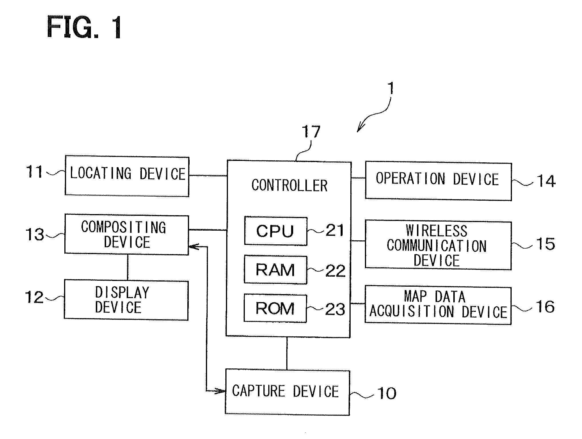
[0042]A first embodiment will be described. FIG. 1 is a diagram illustrating a configuration of a navigation apparatus for a vehicle according to the present embodiment. The navigation apparatus 1 is mounted to a vehicle, and includes a video capture device 10, a locating device 11 (also called herein a position detection device 11), a display device 12 (also called herein an image display device 12), a plane compositing device 13, an operation device 14, a wireless communication device 15, a map data acquisition device 16 and a controller 17 (also called a control device 17).

[0043]The video capture device 10 receives an analog video signal from an on-board video output device (not shown) such as an on-board camera, an on-board video output device and the like, and outputs image data to the plane compositing device 13 in accordance with the received video signal. The video capture device 10 can acquire and record image data that is outputted from the plane compositing device 13 to t...

second embodiment

[0120]A second embodiment will be described below.

[0121]In addition to the operations described in the first embodiment, the navigation apparatus 1 for a vehicle of the present embodiment is configured to perform a screen scrolling operation by utilizing the video capture device 10.

[0122]Specifically, in the display control process, the CPU 21 of the navigation apparatus 1 allows screen scrolling while utilizing the video capture device 10, when display content (i.e., content displayable to a user) is lager than the display screen (corresponding to the portion 41 in FIG. 6) of the display device 12. The display content lager than the display screen of the display device 12 is for example a map, display content (information) received from a Web server via the wireless communication device 15, the capture image from the video capture device 10, or the like.

[0123]In such a case, the CPU 21 executes a predetermined program and thereby performs a scroll process illustrated in FIGS. 13 an...

third embodiment

[0140]A third embodiment will be described below.

[0141]In addition to the operations described in the first and second embodiments, the navigation apparatus 1 for a vehicle of the present embodiment is configured to perform an operation to keep the display on the display device 12 normal during reset of the plane compositing device 13.

[0142]To do so, the CPU 21 of the present embodiment performs a rest process illustrated in the FIG. 16 in resetting the plane compositing device 13. In a case of instant reset, the CPU 21 implements the reset process by, executing a predetermined program.

[0143]At the start of the reset process, the second compositing circuit 13e receives the image data from the first compositing circuit 13d and outputs the received image data to the display, device 12 with no change as usual.

[0144]At S310, the CPU 21 controls the video capture device 10 so that the video capture device 10 records, in the addition plane 22d of the RAM 22, the image data outputted from ...


PUM


Abstract

An image display control apparatus is disclosed. The image display control apparatus stores first layers for original image data in first planes, combines the first layers into the original image data, records the original image data in an addition plane, and stores second layers for replacement image data in second planes. The second layers in the second planes and the original image data in the addition plane are respectively, synchronously and cyclically inputted to a compositing circuit so that the compositing circuit combines the second set of layers into the replacement image data. In the synchronous and cyclical input, the display of the display device is switched from the original image data to the replacement image data while a manner of combining the original image data and the replacement image data is being gradually changed between consecutive frames.

Description

CROSS REFERENCE TO RELATED APPLICATION[0001]The present application is based on and claims priority to Japanese Patent Application No. 2009-292848 filed on Dec. 24, 2009, disclosure of which is incorporated herein by reference.BACKGROUND OF THE INVENTION[0002]1. Field of the Invention[0003]The present invention relates to an image display control apparatus.[0004]2. Description of Related Art[0005]A known image display control apparatus uses a multi-layer compositing technique to display a single image sheet on a display device (see Patent Documents 1 to 3). More specifically, multiple planes (memory area) are prepared. Data of multiple image sheets (called also layers) are respectively stored in the multiple planes. The stored multiple layers are combined into data of a single image sheet by a plane compositing device. The data of the single image sheet is outputted to the display device, and the single image sheet is displayed on the display device.[0006]Patent Document 1: JP-2008-...

Claims


Application Information

Patent Timeline
IPC IPC(8): H04N5/262G09G5/00
CPCG09G5/395G09G2340/0407G09G2340/10H04N5/445H04N5/44504H04N21/4316H04N21/44012G09G5/14H04N21/41422
Inventor NAGATA, MITSUTOSHI
Owner DENSO CORP
Learn More