
Detonator system with high precision delay

a technology of detonator and delay, which is applied in the direction of incandescent ignition, combustion process, combustion ignition, etc., can solve the problems of reducing the range of circuitry that can be used and the length of time it can be used without exhausting power, affecting the magnitude of delays that can be achieved, and unable to detect the different characteristics of an incoming non-electric impulse with a redundancy, etc., to achieve the effect of reducing the cost of production and maintenan

Inactive Publication Date: 2011-06-30
IND MINCO S A C
View PDF5 Cites 32 Cited by
  • Summary
  • Abstract
  • Description
  • Claims
  • Application Information

AI Technical Summary

Benefits of technology

[0011]It is still another object of the present invention to provide a detonation system with redundant independent circuits that permit energy savings.
[0012]It is yet another object of this invention to provide such a detonation system that is inexpensive to manufacture and maintain while retaining its effectiveness.

Problems solved by technology

None of them, however, includes the detection of the different characteristics (pressure / shock, light emission, and heat) of an incoming non-electric impulse with a redundancy in order to avoid false detonations.
To obtain the electrical energy, most systems rely on the energy transmitted through a shock tube, but this approach limits the circuitry that can be utilized as well as the length of the time it can be used without exhausting the power acquired through a piezoelectric generator.
The latter limitation also affects the magnitude of the delays that can be achieved.
The disclosures in U.S. Pat. Nos. 5,435,248 and 5,377,592, to the extent that they use a capacitor only to store energy for the pertinent electronic circuits, have power limitations that can result in the failure of their systems to operate.
The selection of a combination of low power batteries to permit a system to last for days while keeping it rated value below a threshold that could accidentally activate the primary explosive charge in the electric detonator is a problem in the industry.

Method used


Image

  • Detonator system with high precision delay
  • Detonator system with high precision delay
  • Detonator system with high precision delay

Examples


Embodiment Construction

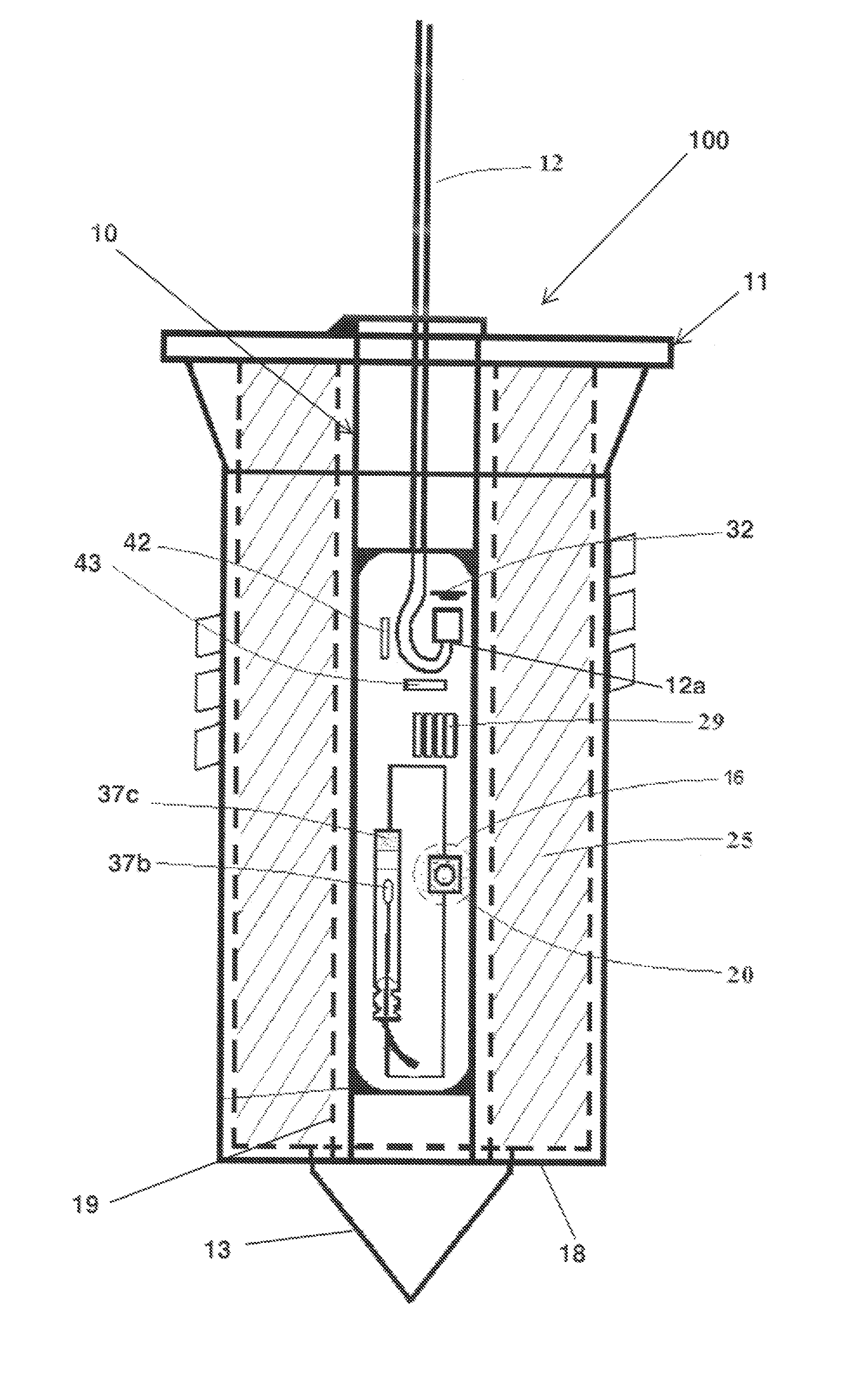
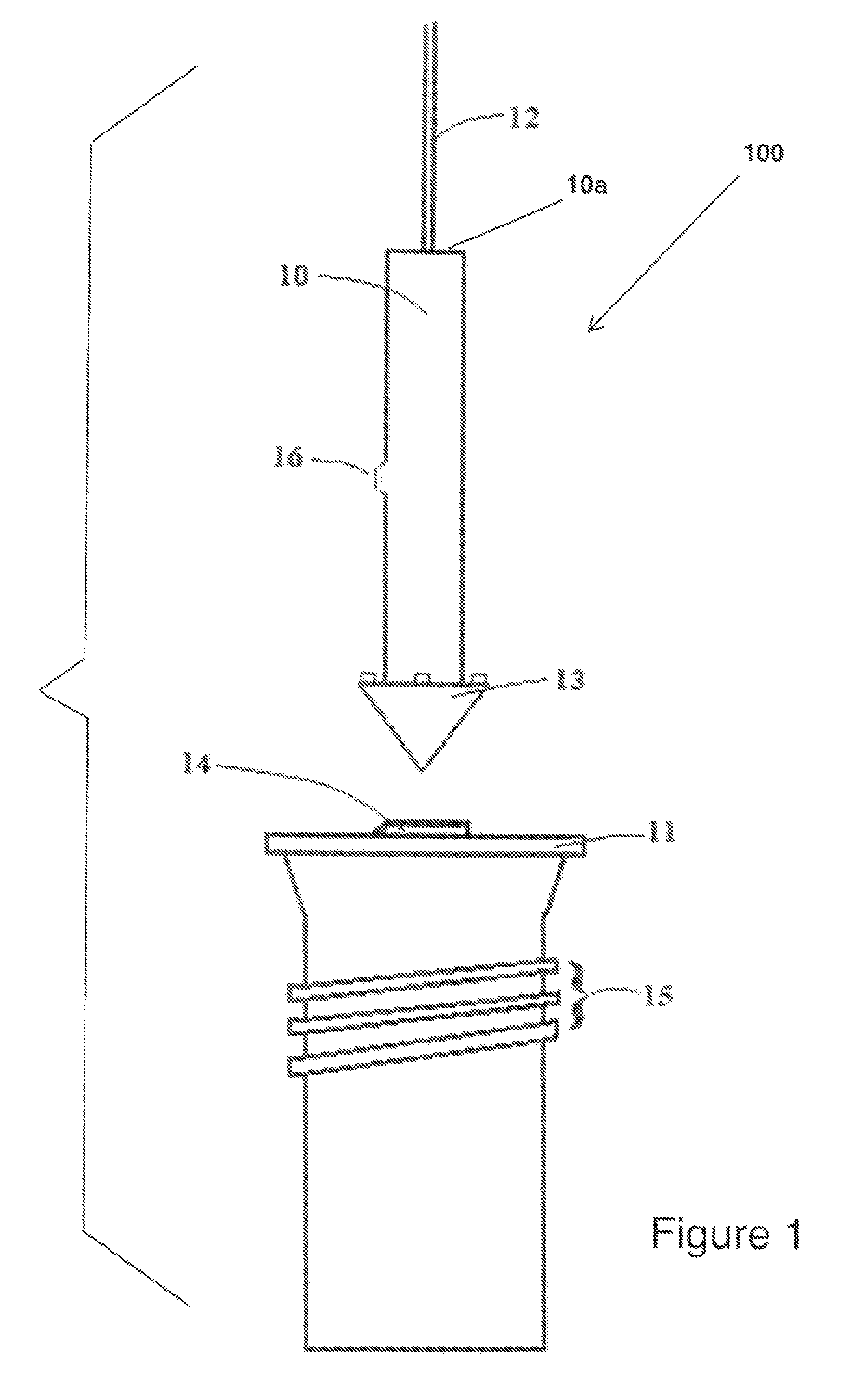
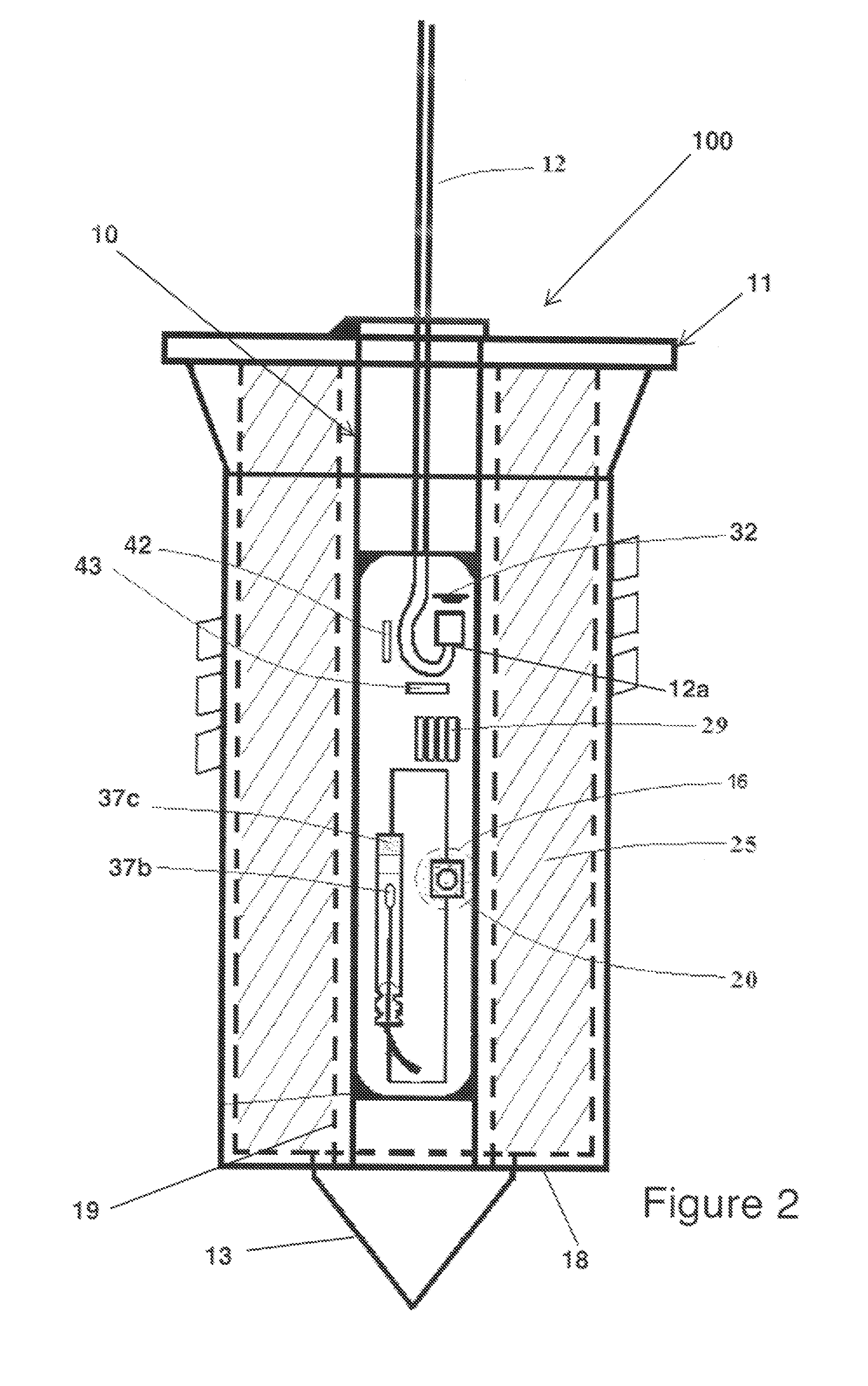
[0024]Referring now to the drawings, where the present invention is generally referred to with numeral 100, it can be observed that it basically includes detonator container or housing 10 with an open end 10a through which shock tube 12 enters and main charge assembly 11 cooperatively receives therein container 10. Latch assembly 14 engages container 10. As seen in FIG. 1, container 10 includes foldable anchorage member 13, having a substantially conical shape in one of the embodiments. FIG. 1 also shows a flexible membrane 16 that is cammingly pushed in when container 10 is inserted inside assembly 11. Assembly 11 includes main explosive charges 25. Membrane 16 is intended to prevent the entry of foreign material inside container 10. This mechanical displacement actuates switch 20, as shown in FIG. 2, thereby activating some of the circuits inside the container. As seen in FIG. 2, a portion of shock tube 12 penetrates inside container 10, which in turn is completely housed within a...


PUM


Abstract

An electrical delay detonator for use in blasting initiation systems energized by a non-electric impulse signal transmitted through a non-electrical conduit, such as a shock tube, with one end inserted inside a detonator housing having redundant sensors for detecting the presence of a non-electric impulse signal and a computerized control circuit for actuating the firing circuit. An elevated voltage is generated, stored in a capacitor assembly, and discharged when fired to an electrically operable igniter. The igniter, when activated, detonates an explosive mass. A battery is also contained within the detonator housing for powering the control circuit and one sensor, in low consumption mode, for several days. Upon detecting the presence of a signal the rest of the circuits are powered up. Periodic time windows generated by the control assembly provide corresponding enabled time periods for the sensors to become operational.

Description

BACKGROUND OF THE INVENTION[0001]1. Field of the Invention[0002]The present invention relates to a detonator (or blasting cap) system with high precision delay, and more particularly, to such a detonator system for mining, quarrying, and construction where the sequencing of detonation of output charges is important to achieve predetermined results.[0003]2. Description of the Related Art[0004]Several designs for detonator systems have been designed in the past. None of them, however, includes the detection of the different characteristics (pressure / shock, light emission, and heat) of an incoming non-electric impulse with a redundancy in order to avoid false detonations. The prior art systems utilizing non-electrical impulses only use the shock characteristic typically to activate a piezoelectric generator. The present invention detects the additional characteristics of a non-electrical impulse, such as the light emitted, its pressure, and its spark. The present invention does not dep...

Claims


Application Information

Patent Timeline
Patent Type & Authority Applications(United States)
IPC IPC(8): F42B3/10F23Q21/00
CPCF42B3/122F42B3/16F42C11/06F42D1/06F42D1/043F42D1/05F42D1/055F42C15/32
Inventor PEREZ CORDOVA, PIO FRANCISCOTREJO MAGUINA, JUAN CARLOS
Owner IND MINCO S A C
Learn More