
Systems and methods for predictive building energy monitoring

Active Publication Date: 2011-06-23
YARDI SYST
View PDF5 Cites 65 Cited by
  • Summary
  • Abstract
  • Description
  • Claims
  • Application Information

AI Technical Summary

Benefits of technology

[0011]A computer readable medium according to an embodiment of the present invention is provided, comprising executable instructions to receive historical building energy load values and corresponding historical predictor variable data comprising values for one or more predictor variables; define a scaling factor for each said predictor variable by cross-validation error minimization for said historical building energy load values using said corresponding historical predictor variable values scaled by said scaling factor values; receive measured building energy load values measured by at least one building energy meter; receive measured predictor variable values corresponding to the measured building energy load values from a predictor variable datasource; determine a predicted building energy load value by kernel smoothing of one or more nearest neighbor historical building energy load values using said defined scaling factors for scaling each said predictor variable; compare said predicted building energy load value with said measured building energy load value to determine if an alert threshold level is exceeded; and to transmit an alert signal to a user when said alert threshold level is exceeded.
[0012]A computer implemented method of building energy monitoring is provided according to another embodiment of the invention, the method comprising receiving historical building energy load values and corresponding historical predictor variable data comprising values for one or more predictor variables; defining a scaling factor for each predictor variable by cross-validation error minimization for the historical building energy load values using corresponding historical predictor variable values scaled by said scaling factors;

Problems solved by technology

However, such physical building models may be very complex, and as a result typically require extensive building-specific evaluation and analysis of design factors by skilled professionals to produce accurate models.
Therefore, the use of such physical building model methods to generate predicted or typical building energy load values may be impractical for use on multiple dissimilar buildings, due to the computational and economic cost of developing such models for each building.
This approach may also be unsuitable for use in connection with buildings for which detailed design data is not available or impractical to obtain.
However, models based on such polynomial functions may not provide a good fit to building energy load data, in particular low order polynomials may be unable to follow step changes and higher order polynomials may overfit to noise.
Also, the use of polynomial functions may result in poor estimated or predicted values for variables outside the range of training datasets.
However, the use of neural network techniques may require complex computation of many parameters in order to fit or learn from a historical building energy load dataset.
This approach may further be prone to unstable or erroneous prediction behavior when used to produce predicted building energy load values corresponding to predictor variable values which are outside the range of the historical dataset used to fit or train the neural network system.
Also, the use of neural network techniques may typically involve the use of a large number of parameters relative to their expressive power, which may contribute to estimation or prediction errors related to overfitting in some applications, depending upon the size and / or range of the historical building energy load dataset available to use in training or initializing of a neural network model.

Method used


Image

  • Systems and methods for predictive building energy monitoring
  • Systems and methods for predictive building energy monitoring
  • Systems and methods for predictive building energy monitoring

Examples


Embodiment Construction

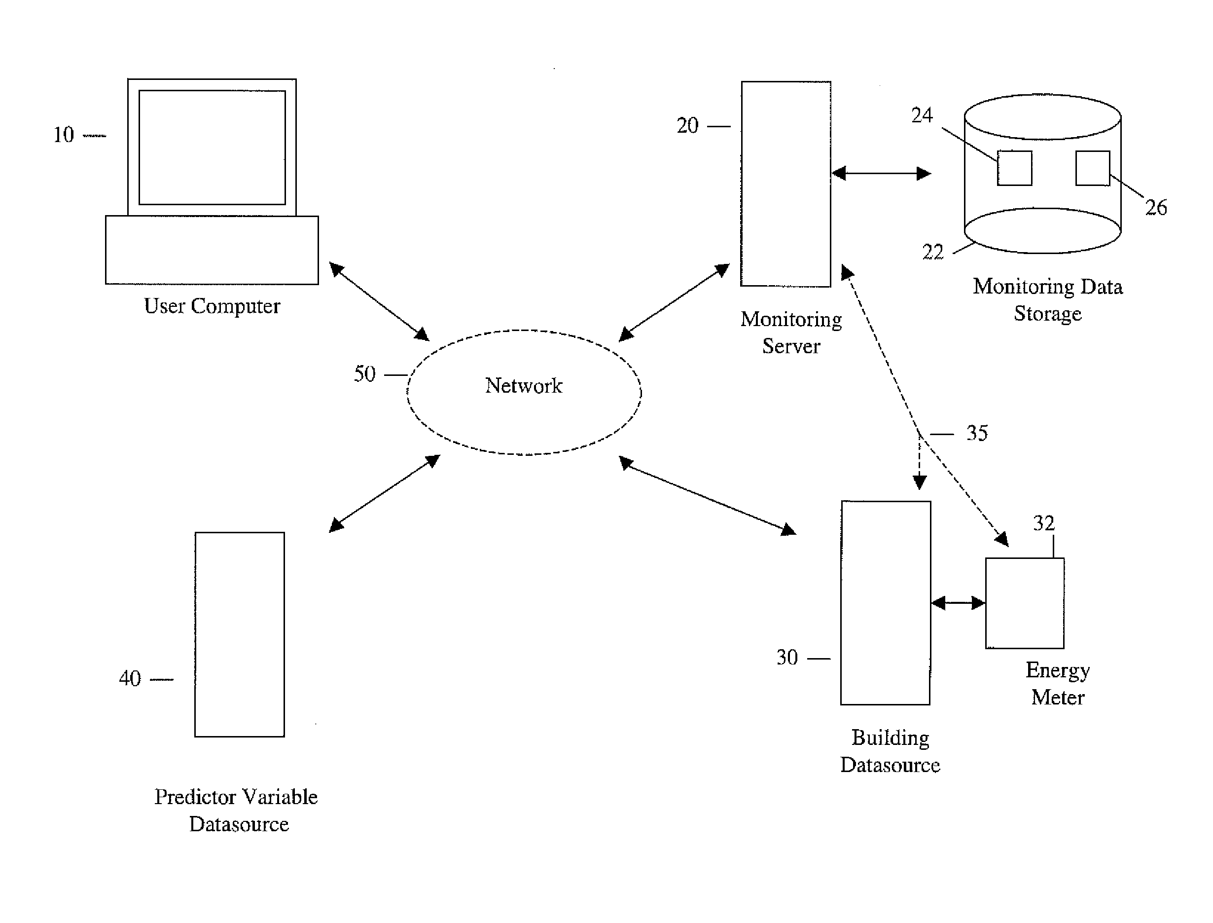
[0024]FIG. 1 illustrates an exemplary networked operating environment in which an embodiment of the present invention may be implemented. The networked environment includes a user computer 10 connected to a communication network 50, which may include one or more of: a local area network, intranet, wide area network, world wide web (WWW), or the global Internet, for example, such that user computer 10 may communicate with other computers similarly connected to network 50. Other computers connected to network 50 may include a building monitoring server 20, building datasource server 30 connected to building energy meter 32, and a predictor variable datasource server 40, which may each communicate with any other computer connected to the network 50. Optionally, building datasource server 30 may connect directly to building monitoring server 20, such as by connection 35, for example. Additionally, in a further optional embodiment, building energy meter 32 may connect directly to buildin...


PUM


Abstract

A system and method for predictive modeling of building energy consumption provides predicted building energy load values which are determined using kernel smoothing of historical building energy load values for a building using defined scaling factors for scaling predictor variables associated with building energy consumption. Predictor variables may include temperature, humidity, windspeed or direction, occupancy, time, day, date, and solar radiation. Scaling factor values may be defined by optimization training using historical building energy load values and measured predictor variable values for a building. Predicted and measured building energy load values are compared to determine if a preset difference threshold has been exceeded, in which case an alert signal or message is generated and transmitted to electronically and / or physically signal a user. The building energy monitoring system may be integrated with a building automation system, or may be operated as a separate system receiving building energy and predictor variable values.

Description

1. TECHNICAL FIELD[0001]The present invention relates generally to systems and methods for building energy management. More specifically, the present inventive systems and methods relate to building energy monitoring using predicted building energy use values.2. BACKGROUND OF THE INVENTION[0002]As the desire to improve energy efficiency has become more widespread, a need for effective methods and infrastructure to monitor and control the consumption of energy by buildings of all sizes has become of increasing importance, and for large buildings in particular. As a result, building management systems have become increasingly common. Building management systems typically provide for the measurement and control of building energy systems, including the measurement of consumption of various energy-related resources by building systems including for example electrical energy, natural gas, thermal energy, steam energy, or water usage, through the use of electronic and / or computerized buil...

Claims


Application Information

Patent Timeline
IPC IPC(8): G06F1/26G08B21/00
CPCF24F2011/0047F24F2011/0075G06Q10/04G06Q50/06H02J3/00H02J2003/003Y02B90/2638Y04S40/124H02J13/0062F24F2140/60F24F11/46H02J3/003H02J13/00016Y02B90/20
Inventor BROWN, MATTHEWBARRINGTON-LEIGH, CHRISTOPHERPORTER, CHRISTOPHER
Owner YARDI SYST
Learn More