
Regenerative switched reluctance motor driving system

a technology of switched reluctance motors and driving systems, applied in the direction of motor/generator/converter stoppers, electronic commutators, dynamo-electric converter control, etc., can solve the problems of complex structure, lack of practical use, and reducing the efficiency of three-phase induction motors, so as to improve the energy recovery efficiency, reduce the size and weight, and increase the efficiency of the switched reluctance motor

Inactive Publication Date: 2011-06-23
MOTOR SYST
View PDF22 Cites 6 Cited by
  • Summary
  • Abstract
  • Description
  • Claims
  • Application Information

AI Technical Summary

Benefits of technology

[0014]The regenerative switched reluctance motor driving system of the present invention can achieve a reduction in the size and weight and an increase in the efficiency of the switched reluctance motor and an improvement in the energy recovery efficiency at the time of regenerative braking without using a neodymium magnet.

Problems solved by technology

On the other hand, the pseudo sine wave output from a PWM inverter has many harmonic components, which is a cause of resisting torque.
This significantly reduces the efficiency of the three-phase induction motor.
Furthermore, although regenerative braking is theoretically possible, it is necessary to separately provide an inverter for regeneration, resulting in a complex structure.
However, it lacks practical use at present because there is no basis for its superiority to the motor driving system (3) described above, and particularly because there is no specific method of electric braking.

Method used


Image

  • Regenerative switched reluctance motor driving system
  • Regenerative switched reluctance motor driving system
  • Regenerative switched reluctance motor driving system

Examples


example 1

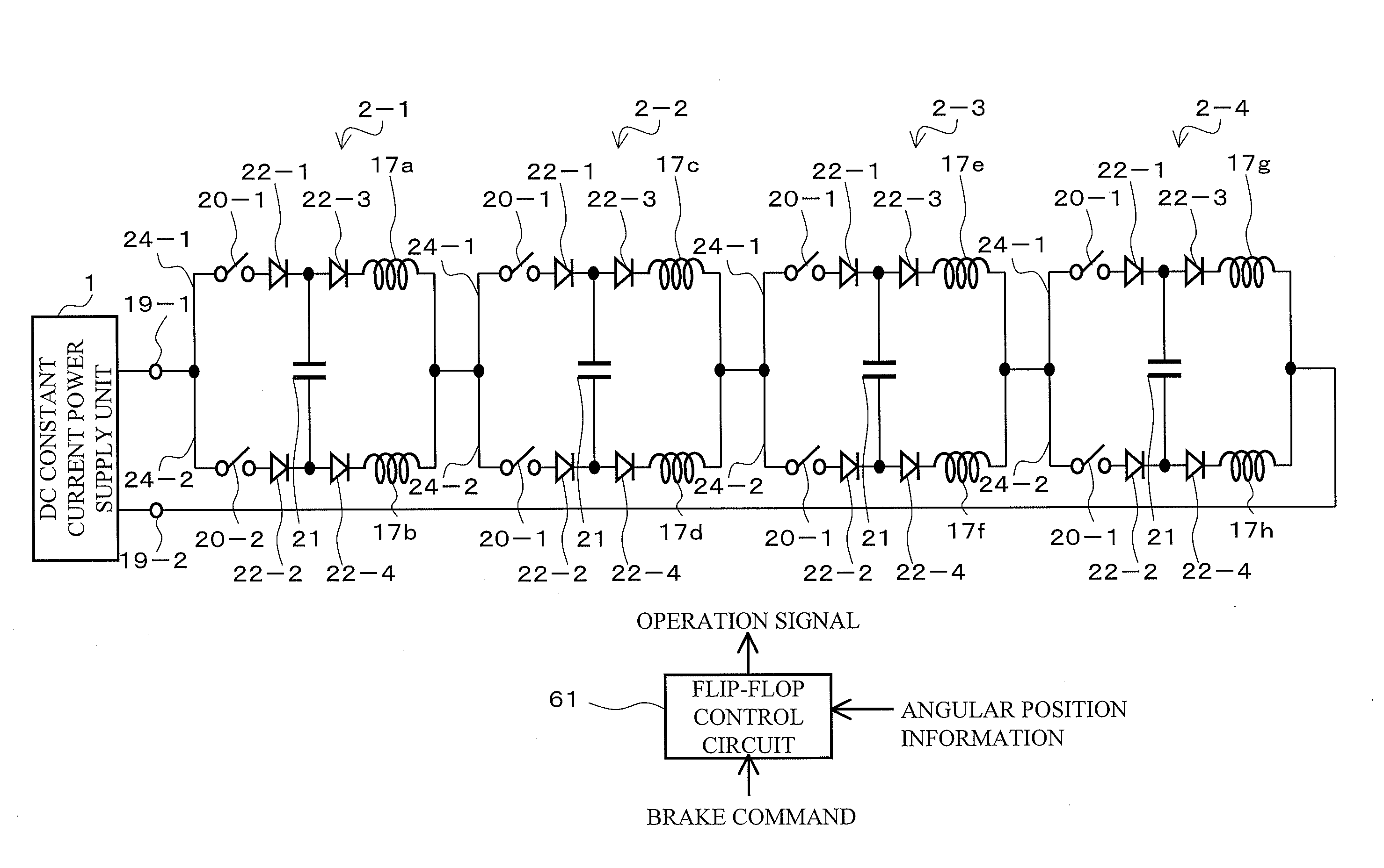
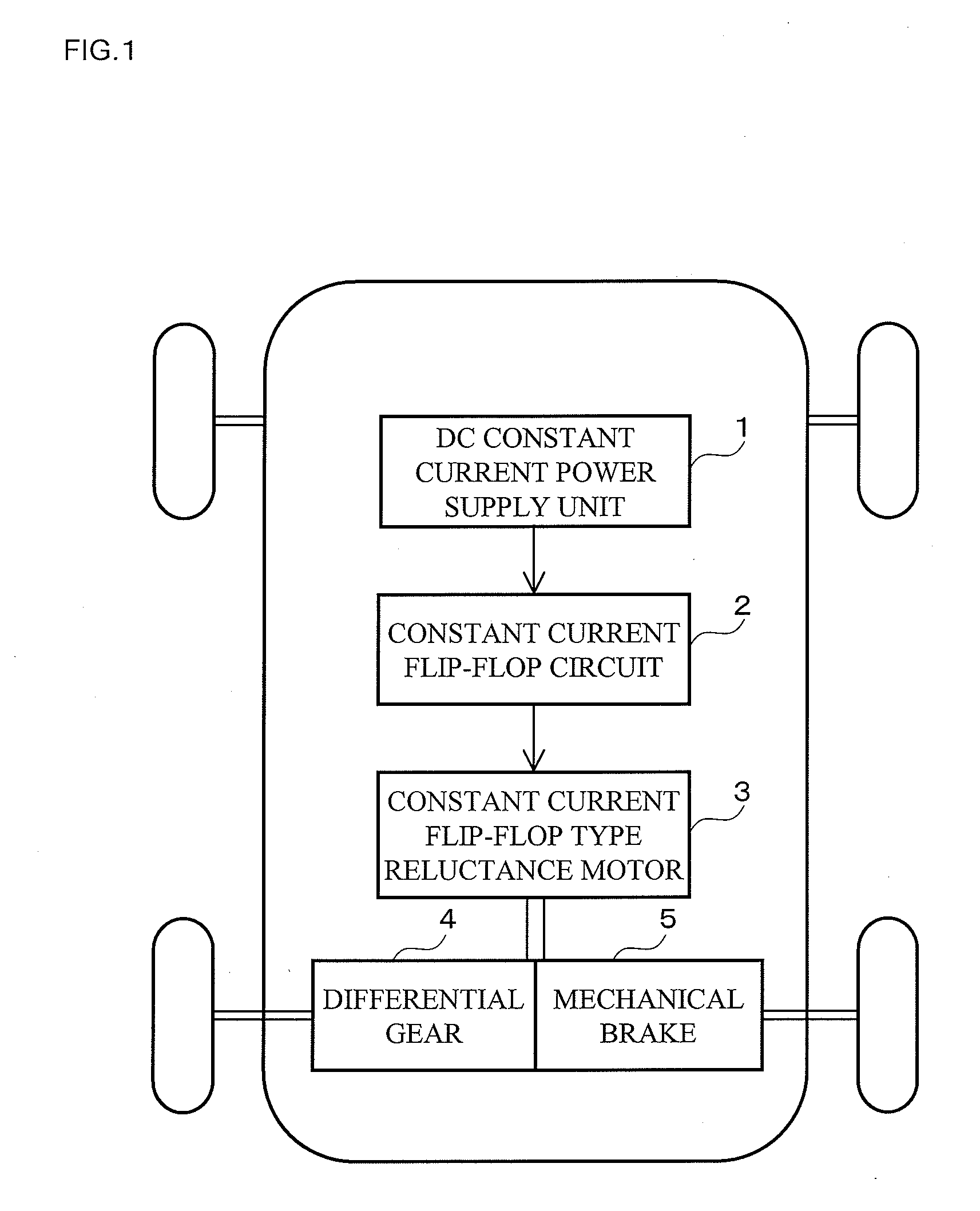
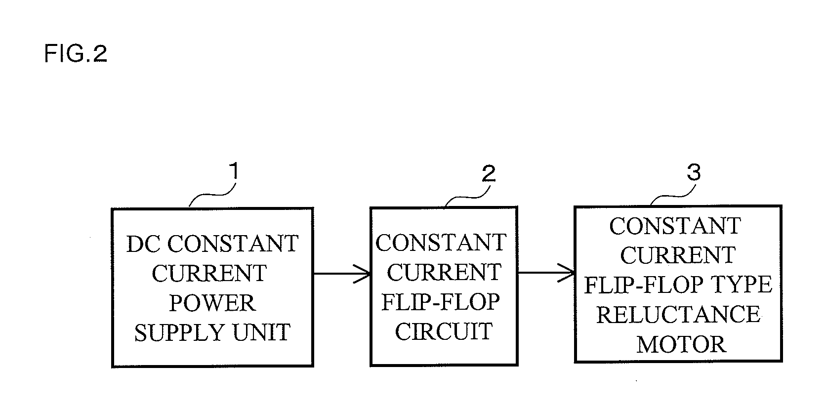
[0056]FIG. 1 shows a structure of an electric car to which a regenerative switched reluctance motor driving system according to an embodiment of the present invention is applied. Referring to FIG. 1, the electric car has a DC constant current power supply unit 1, a constant current flip-flop circuit 2, a constant current flip-flop type reluctance motor 3 as a regenerative switched reluctance motor, a differential gear 4 and a mechanical brake 5. Among them, the regenerative switched reluctance motor driving system according to the embodiment of the present invention mainly comprises the DC constant current power supply unit 1, the constant current flip-flop circuit 2 and the constant current flip-flop type reluctance motor 3. Note that although only one multi-phase constant current motor 1 is provided in FIG. 1, it can also be structured to place one for each tire to omit the differential gear 4. In the regenerative switched reluctance motor driving system according to the embodimen...


PUM


Abstract

Provided is a regenerative switched reluctance motor driving system which allows a motor to have a reduced size and weight and an increased efficiency as well as improved energy recovery efficiency at the time of regenerative braking without using a neodymium magnet. Based on an angular position of a rotor in the motor, a constant current flip-flop circuit 2 renders two current paths alternately conductive so as to allow a rectangular-wave current having a width of an electrical angle of 180° to alternately flow in two coils in the motor 3, and shifts the timing of rendering the two current paths alternately conductive, between when driving and when braking the motor 3, by a time during which the rotor is rotated by an angle corresponding to an electrical angle of 180°. When driving the motor, a DC constant current power supply unit 1 discharges a DC power supply, while when braking the motor, it receives an input current through a negative terminal of the DC power supply, and outputs a DC current to the constant current flip-flop circuit 2, and further outputs a DC current regenerated from the motor 3 through the constant current flip-flop circuit 2 to a positive terminal of, and thereby charges, the DC power supply.

Description

TECHNICAL FIELD[0001]The present invention relates to a regenerative switched reluctance motor driving system using a regenerative switched reluctance motor for driving an electric car or the like.[0002]BACKGROUND ART[0003]Currently, in representative motor driving systems using a DC power supply, that have been commercialized or proposed, there are (1) those comprising a PWM inverter and a three-phase synchronous motor, (2) those comprising a constant current power supply, a multi-phase constant current inverter and a multi-phase constant current motor, (3) those comprising a PWM inverter and a three-phase induction motor, and (4) those comprising a switched reluctance motor (e.g. Patent Document 1).[0004]The motor driving system (1) has existed for many years, and has advanced rapidly in the last few years by using a strong neodymium magnet in the motor. The motor driving system (2) was invented by the same inventor as the present invention, and makes it possible to reduce the siz...

Claims


Application Information

Patent Timeline
Patent Type & Authority Applications(United States)
IPC IPC(8): H02P3/14H02P3/18H02P25/08
CPCB60L7/10B60L2220/18H02K19/103B60L2200/26H02P25/08Y02T10/641Y02T10/642H02P3/14Y02T10/64
Inventor UMEMORI, TAKASHITANAKA, MAKOTO
Owner MOTOR SYST
Learn More