
Sealing arrangement

a sealing arrangement and sealing technology, applied in the direction of engine seals, mechanical equipment, engine components, etc., can solve the problems of contaminated second medium and drying out the middle space, and achieve the effect of simple construction

Inactive Publication Date: 2011-06-23
VON ARDENNE ANLAGENTECHNIK GMBH
View PDF9 Cites 5 Cited by
  • Summary
  • Abstract
  • Description
  • Claims
  • Application Information

AI Technical Summary

Benefits of technology

[0008]It is an object of the invention to enable an early detection of the risk of leakage in the sealing lip disposed on the medium side by means of a simple construction of the sealing system and to prevent, as far as possible, the leakage of the first medium from wetting the second sealing lip.
[0013]In a development of the invention, a third sealing element is provided that is disposed in the axial direction of the first machine element at a distance from the first sealing element, the intermediate space between the first sealing element and the third sealing element comprising an outlet for the drainage or suction of the rinsing medium and possible leakages. This third chamber comprising the associated outlet for suction once again improves the sealing effect of the sealing arrangement considerably.
[0014]The inlet for the rinsing medium and / or the first outlet and / or the second outlet for drainage or suction can each be guided from the outside toward the inside through the sealing arrangement into the first chamber. This embodiment can be advantageous particularly for rotating first machine elements in order to simplify the supply and removal of media.
[0015]The inlet for the rinsing medium and / or the first outlet and / or the second outlet for drainage or suction can each also be guided from the inside toward the outside through the first machine element into the first chamber. This embodiment can be advantageous particularly for rotating first machine elements, when the supply and removal of media are intended to be carried out from the vacuum side, or for stationary first machine elements.
[0016]The sealing arrangement suggested herein is suitable, for example, for a rotary feedthrough that is loaded by coolant pressure and that is intended to protect a space located on the atmosphere side from leakage by means of two rotary seals.

Problems solved by technology

It is also known that some solutions used in coolant seals cause the intermediate space to be dried out by blowing out the leak.
In the case of a leak in the sealing lip, the second medium becomes contaminated.

Method used


Image

  • Sealing arrangement
  • Sealing arrangement
  • Sealing arrangement

Examples


Embodiment Construction

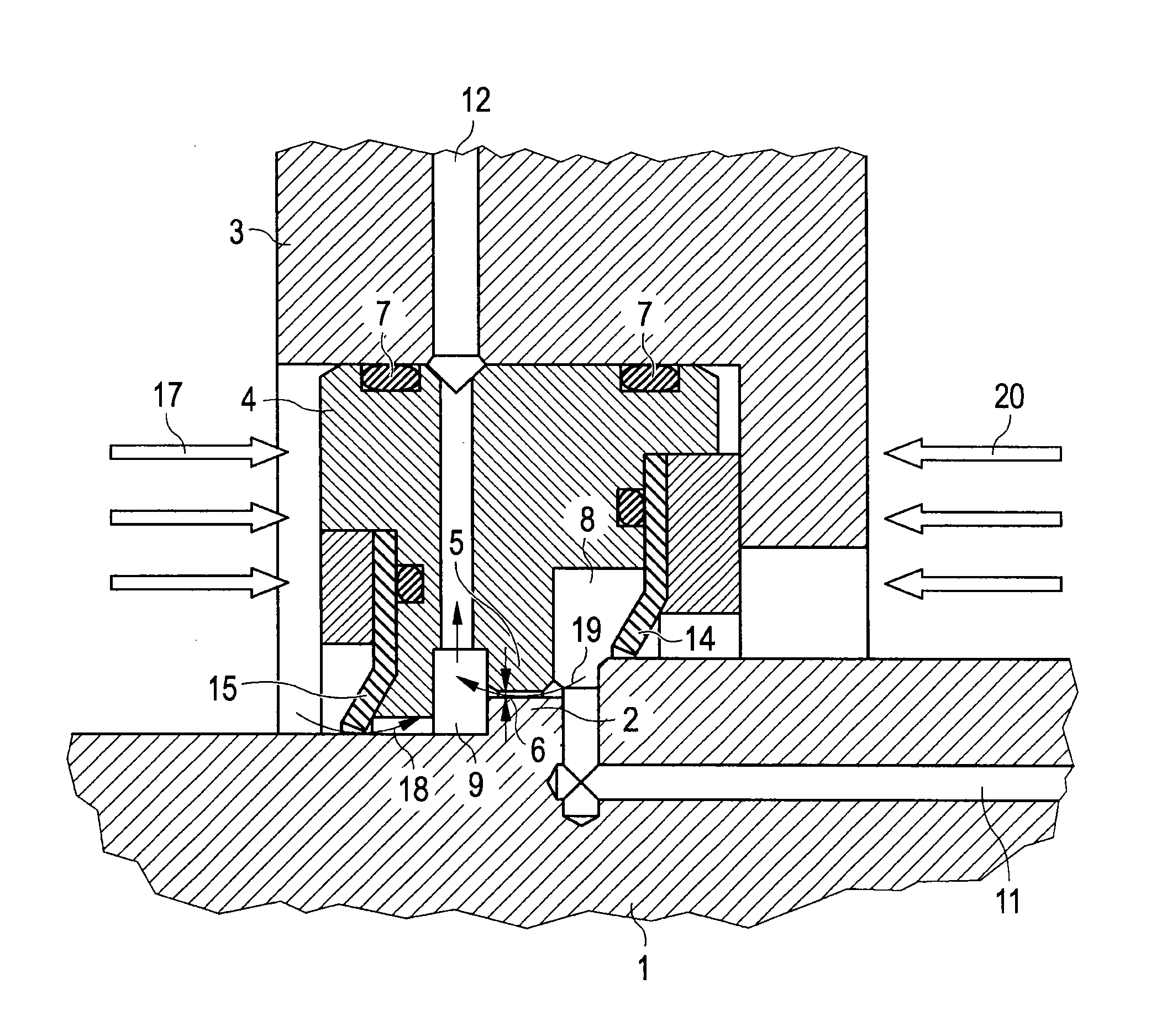
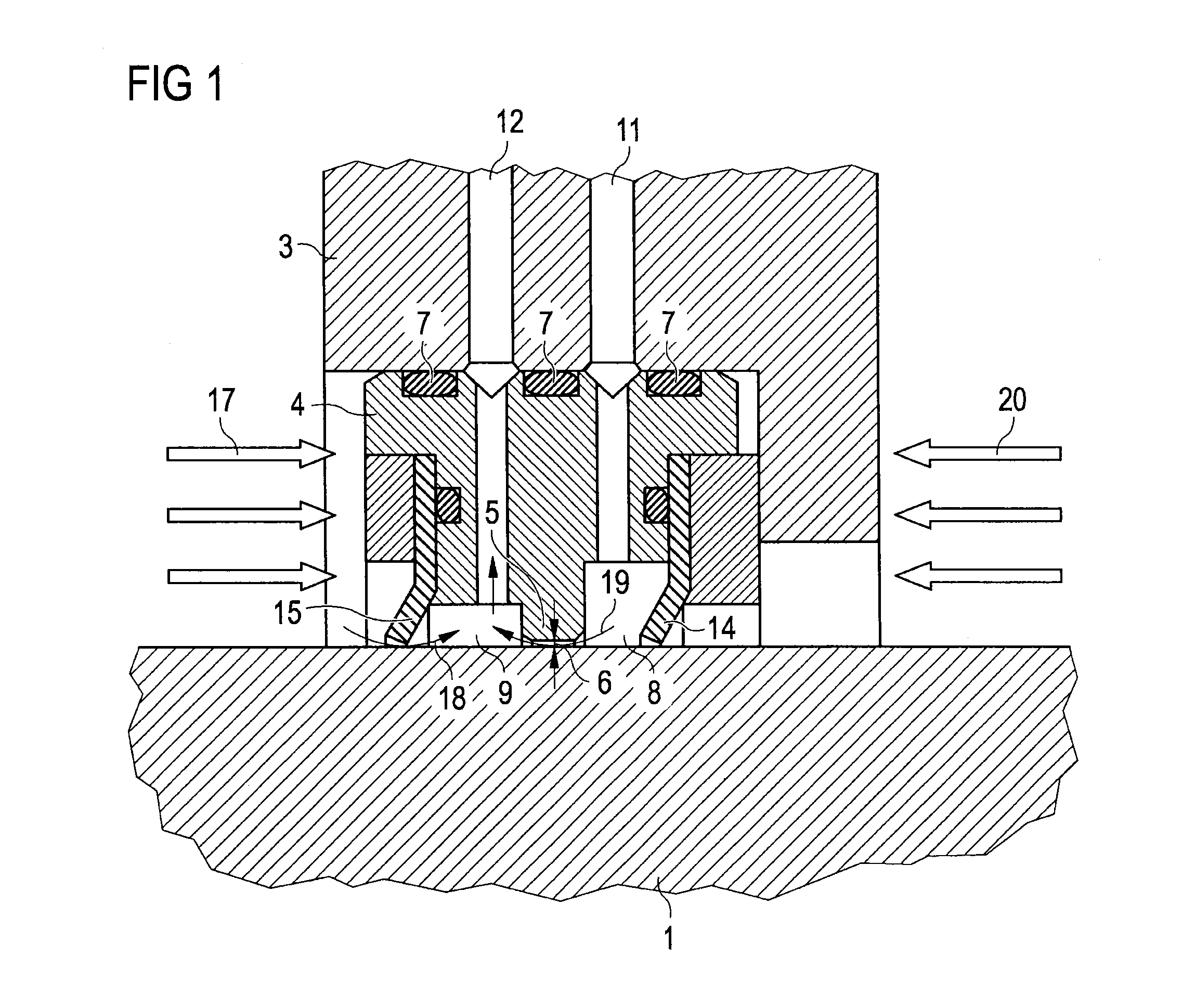
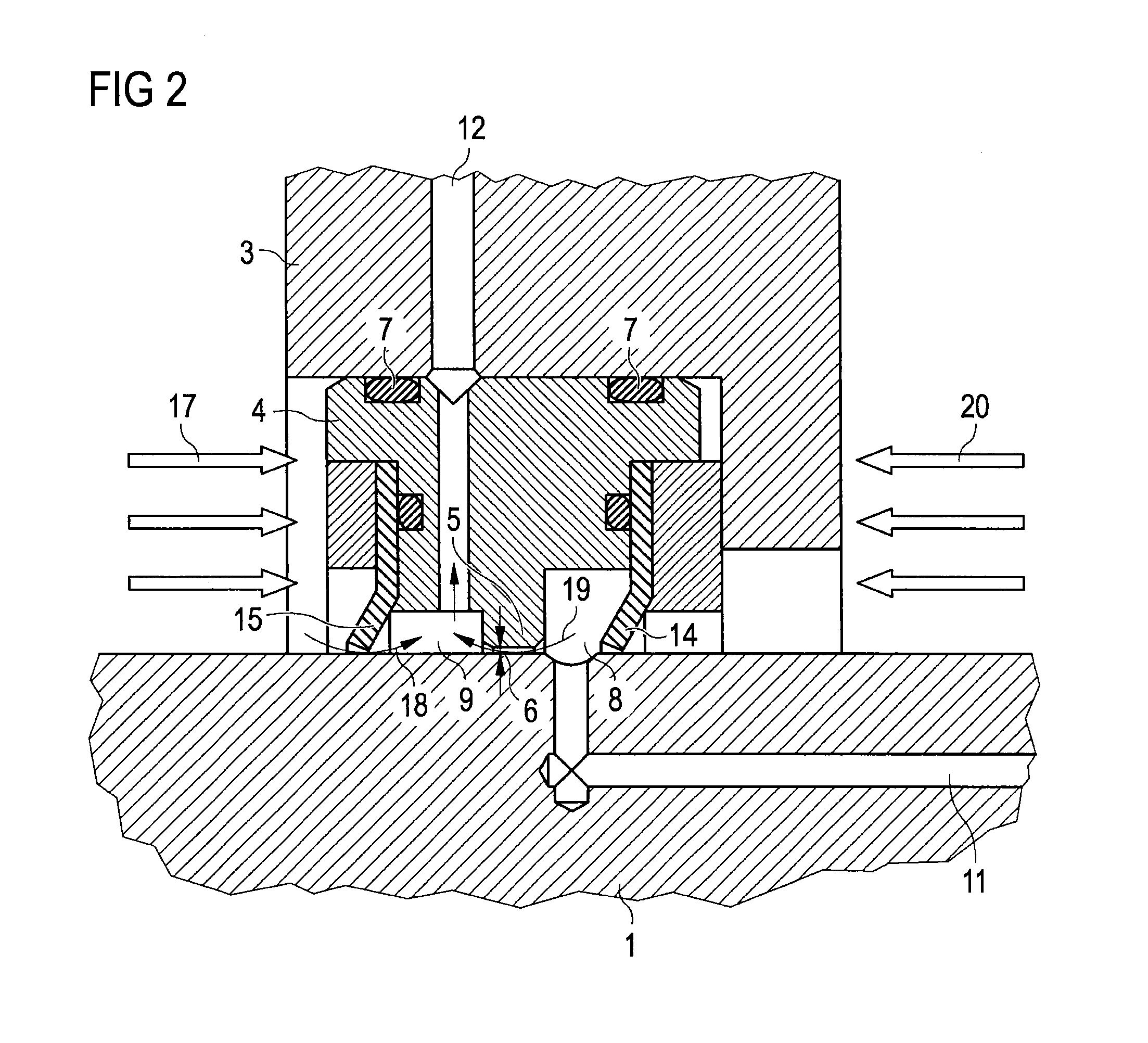
[0025]In the exemplary embodiments shown in FIGS. 1 to 3, the sealing arrangement comprises a separate base body 4 that is sealed by outer sealing elements 7 in relation to the second machine element 3.

[0026]On this base body 4, there is disposed a first sealing element 14 and a second sealing element 15 that form a sealing connection with the first machine element 1, for example, a shaft. The first sealing element 14 separates the rinsing medium 19 (e.g. dry compressed air) from the atmosphere 20. The second sealing element 15 separates coolant 17 from the rinsing medium 19.

[0027]The base body 4 comprises a circumferential rib 5 that has an inside diameter that is slightly larger than the outside diameter of the shaft 1 so that an annular gap 6 is formed. Advantageously, the annular gap 6 is disposed around the circumference of the shaft 1; however, other arrangements of the annular gap 6 are also possible as explained in more detail below in the description of the individual figur...


PUM


Abstract

A sealing arrangement for a feedthrough is located between a first machine element and a second machine element and comprises a first sealing element, and a second sealing element disposed in the axial direction of the first machine element at a distance from the first sealing element. The inner sides of the sealing elements form a sealing operative connection with the first machine element. An intermediate space between the first sealing element and the second sealing element is divided into a first chamber and a second chamber connected to each other by an annular gap between the first machine element and the sealing arrangement. The first chamber includes an inlet for a rinsing medium and the second chamber includes a first outlet for drainage or suction of the rinsing medium and possible leakages.

Description

CROSS REFERENCE TO RELATED APPLICATIONS[0001]This application claims priority of German application DE 10 2009 059 099.4 filed on Dec. 18, 2009 and German application DE 10 2010 027 757.6 filed on Apr. 14, 2010, the entire contents of both of these applications being hereby incorporated by reference herein.BACKGROUND ART[0002]The invention relates to a sealing arrangement that can be used for static seals, but also for rotary feedthroughs such as those used in vacuum-processing facilities by way of example. Sealing arrangements of this type are described in DE 10 2009 014 214, for example.[0003]Rotary feedthroughs are needed in order to guide rotating parts such as shafts through housing walls and the like when the driving machine element, e.g. a drive arrangement, is disposed on one side of the housing wall and the machine element to be driven, e.g. a rotating target, is disposed on the other side of the housing wall. By contrast, static feedthroughs serve for guiding stationary co...

Claims


Application Information

Patent Timeline
IPC IPC(8): F16J15/02
CPCF16J15/004F16J15/002
Inventor GROSSER, GOETZHEINRICH, HANS-JUERGENGRUNE, HARALD
Owner VON ARDENNE ANLAGENTECHNIK GMBH
Learn More