Method for manufacturing a disc brake pad

a technology of disc brakes and manufacturing methods, which is applied in the direction of brake types, friction linings, braking elements, etc., can solve the problems of not being able to provide the entire uniformity of friction materials, not being able to provide enough space for powdered raw materials to flow, and making brake noises. the effect of prevention

Active Publication Date: 2011-06-23
NISSHINBO BRAKE INC
View PDF1 Cites 1 Cited by
  • Summary
  • Abstract
  • Description
  • Claims
  • Application Information

AI Technical Summary

Benefits of technology

[0019]Because of the manufacturing method according to this invention, the density of the friction material at the final inclined surface portion is equal to the density of the friction surface portion, and this density equality prevents the brake noises, even if the final inclined surface disappears due to the friction material wear.

Problems solved by technology

However, conventional disc brakes have problems of making brake noises because of disc brake pad and / or disc rotor vibration during the brake operation.
Yet, when the amount of the fibrous materials in the friction material is large and the flowability of the powdered raw materials is not sufficient, the manufacturing method of the Patent Document 1 cannot often provide the entirely uniform friction material.
More specifically, there is not enough space for the powdered raw materials to flow and not enough flowability of the powdered raw materials, thereby providing a disc brake pad having a friction material with a higher density at the final inclined surface portion thereof.

Method used


Image

  • Method for manufacturing a disc brake pad
  • Method for manufacturing a disc brake pad
  • Method for manufacturing a disc brake pad

Examples


Embodiment Construction

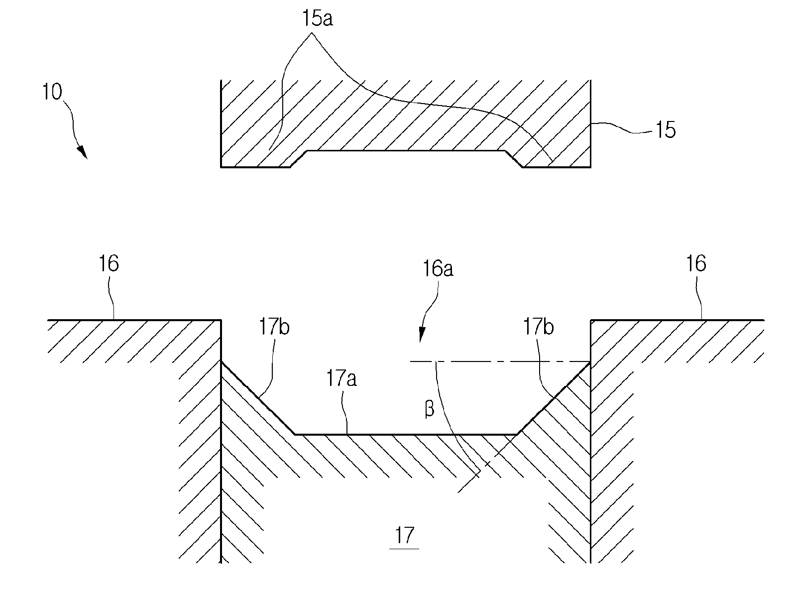
[0028]Preferred embodiments of this invention will be explained with reference to the drawings. FIG. 1 is a view illustrating the metal preliminarily forming die used in the manufacturing process of this invention. The metal preliminarily forming die 10 is a combination of three metal die parts including an upper die 15, a frame die 16, and a plunger 17. These three parts are set in a press machine while the frame die 16 is fixed but the upper die 15 and the plunger 17 are vertically movable. A cross-section shape of a hollow portion 16a of the frame die 16 has the same shape as a shape of the friction material 3 as appeared in FIG. 5(a) viewing for a plane, and the hollow portion 16a vertically penetrates through the frame die 16. The plunger 17 is vertically movable within the hollow portion 16a. Also, a plan surface 17a is formed at an intermediate portion of an upper surface of the plunger 17, and first inclined surfaces 17b, 17b are formed at both ends thereof. An angle of the ...


PUM

PropertyMeasurementUnit
pressureaaaaaaaaaa
angleaaaaaaaaaa
thicknessaaaaaaaaaa

Abstract

To provide a manufacturing method for a disc brake pad using a forming die to form a final inclined surface on a friction material, where the resulted friction material is entirely uniform even if the flowability of the powdered raw friction material is insufficient. The method for manufacturing a disc brake pad includes the steps of preliminarily forming a preliminarily formed product by pressurizing without heating the powdered raw materials in a metal preliminarily forming die, and forming the final inclined surface on the friction material using a metal forming die with an inclined surface, the step of preliminarily forming including forming a temporary inclined surface, having a larger angle than the final inclined surface of the friction material, on the preliminarily formed product at an opposite side thereof to be fixed to a back plate, and forming a recess portion on the preliminarily formed product at a side thereof to be fixed to the back plate.

Description

CROSS-REFERENCE TO RELATED APPLICATION(S) AND CLAIM OF PRIORITY[0001]The present application claims the benefit under 35 U.S.C. section 119(a) of Japanese Patent Application filed in the Japan Patent Office on Dec. 18, 2009, and assigned serial number 2009-287608, the disclosure of which is incorporated herein by reference.FIELD OF INVENTION[0002]This invention relates to a method for manufacturing a disc brake pad used for motor vehicles, particularly a method for manufacturing a disc brake pad which is capable of eliminating / minimizing brake noises.BACKGROUND OF INVENTION[0003]A disc brake pad for a disc brake of a motor vehicle generally is a combination of a steel back plate and a friction material fixed on the steel back plate. The friction material may be formed by pressurizing and heating a mixture of powdered materials including such as a fibrous material, a filler, and a binder. A disc brake brakes a motor vehicle with a frictional force generated as pressing the disc brake...

Claims


Application Information

Patent Timeline
Patent Type & Authority Applications(United States)
IPC IPC(8): B29C43/14
CPCF16D69/00F16D69/04F16D2069/004F16D2069/0483F16D65/092F16D2069/045B29C43/00B29C43/02
Inventor TOSHIMA, SHINICHIYOSHIHARA, SAKAE
Owner NISSHINBO BRAKE INC
Why Eureka
Try Eureka