Disk brake with a spring arrangement

A technology of disc brake and spring device, applied in the direction of brake components, brake type, mechanical equipment, etc., can solve problems such as disadvantages

Inactive Publication Date: 2009-04-22
CONTINENTAL TEVES AG & CO OHG
View PDF5 Cites 0 Cited by
  • Summary
  • Abstract
  • Description
  • Claims
  • Application Information

AI Technical Summary

Problems solved by technology

However, it has been found that the described spring device is disadvantageous in terms of installation, first of all the installation of the brake pads

Method used


Image

  • Disk brake with a spring arrangement
  • Disk brake with a spring arrangement

Examples


Embodiment Construction

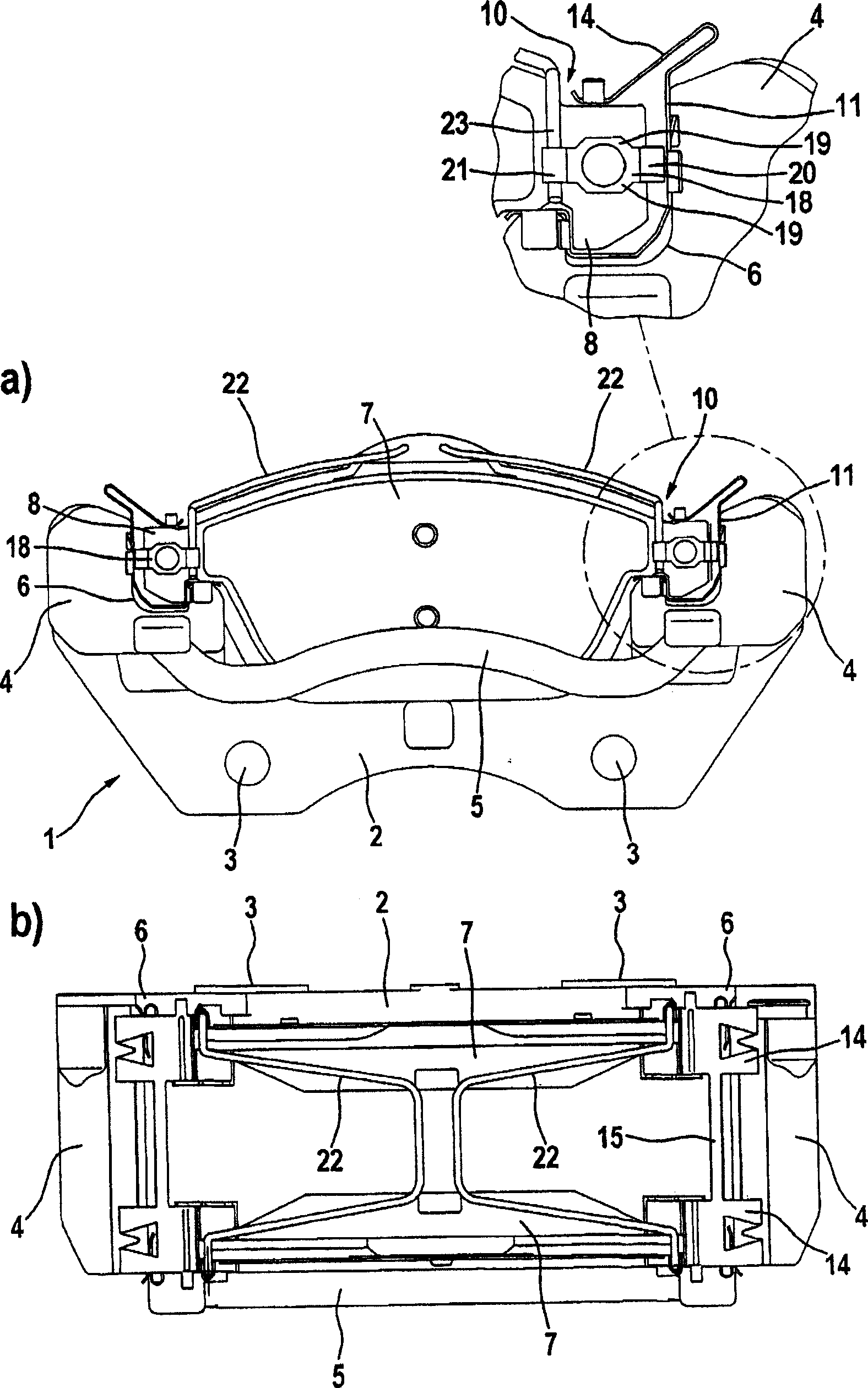
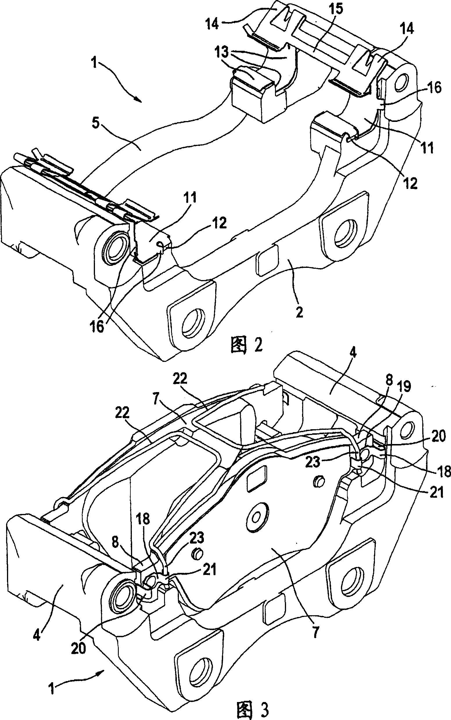
[0015] The brake carrier 1 shown in the figure is a component of a floating-caliper disc brake, as is usually used in motor vehicle braking systems. The brake carrier 1 cooperates here with an associated, but not shown, floating caliper, which is supported axially displaceably on the brake carrier 1 . The brake carrier 1 comprises a base section 2 with fastening holes 3 , via which holes the brake carrier can be mounted in a position-stationary manner or fixedly relative to the vehicle. Attached to the base section 2 is an axially extending support arm 4 which protrudes axially beyond the associated brake disk. To increase the rigidity of the brake carrier, the end of the carrier arm 4 opposite the base section 2 is connected to the web 5 . Formed on the carrier arm 4 is a guide section 6 for receiving a brake shoe 7 which is itself arranged displaceably on the brake carrier 1 . In the guide section 6, each brake shoe 7 is axially movably guided and tangentially supported by...


PUM


Abstract

The invention relates to a disk brake comprising brake linings (7) which are displaceably received on both sides of a disk brake inside guide sections (6) of said disk brake, and a spring arrangement (10) used as springing for the brake linings (7). Said disk brakes are often used in motor vehicles. In order to improve the springing of the brake linings, the spring arrangement (10) comprises at least one radial spring element (11) for radial bracing of the brake linings (7) in relation to the guide sections (6); at least one axial spring element (22) for axial bracing of the brake linings (7) amongst themselves; in addition to at least one tangential spring element (18) for tangential bracing of the disk brakes (7) in relation to the guide sections (6). The three spring elements (11, 18, 22) act in different spatial dimensions and can be embodied in the form of separate components which are independent of each other.

Description

technical field [0001] The invention relates to a spring device for a disc brake, the disc brake having brake pads and a spring device, the brake pads being movable on both sides of the brake disc by the disc brake The guide section is accommodated, and the spring device is used to elastically load the brake pad. Such disc brakes are commonly used in motor vehicles. Background technique [0002] From DE 1023446 A1 is known a brake carrier of a floating-caliper disc brake with a brake pad guide spring, wherein the brake pad guide spring is latched on the brake carrier. The brake shoe guide spring extends between the brake carrier and the corresponding brake shoe and thus ensures ease of movement of the brake shoe. At the same time, the brake shoe guide spring has a spring arm in order to tension the brake shoe relative to the brake carrier without rattling. In this case, the spring arm is designed to allow radial mounting of the brake pad and then radial locking of the bra...

Claims


Application Information

Patent Timeline
Patent Type & Authority Patents(China)
IPC IPC(8): F16D65/097
Inventor U·巴赫H·邦格特J·鲍尔A·塞弗
Owner CONTINENTAL TEVES AG & CO OHG
Why Eureka
Try Eureka